Triguard SC300E TDI16BIA 16-Channel Digital Input Termination Card 24Vdc (TDI16BIA) Issue 3 October 2005 INTRODUCTION PURPOSE The TDI16BIA16-channel digital input termination card acts as an interface between the digital signalling devices in the field device and the digital input circuits of an SC300E chassis.
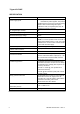
Triguard SC300E SPECIFICATION Model Power supply inputs TDI16BIA Has two separate connectors (FS1and FS2) for redundant dc power supplies. The positive supplies feed a common bus via auctioneering diodes. When auctioneering takes place outside the card, the required power may be supplied via a single connector. No. of digital input channels 16 Nominal field supply voltage 24Vdc Maximum field supply voltage 33Vdc Current rating 50mA per channel.
Triguard SC300E TDI16BIA 16-Channel D/I Termination Card 24Vdc ENVIRONMENTAL SPECIFICATIONS The maximum ambient temperature measured at the hottest point within the Triguard system shall not be greater than 60 degrees centigrade. Temperature operating: +5°C to +60°C Temperature storage: -25°C to +70°C Humidity: 5% to 95% non-condensing at ambient < 40°C The maximum ambient temperature measured at the hottest point within the Triguard system shall not be greater than 60 degrees centigrade.
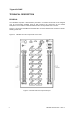
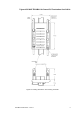
Triguard SC300E TECHNICAL DESCRIPTION PHYSICAL The TDI16BIA comprises a PCB assembly mounted in a moulded carrier that can be snapped onto all commercially available styles of DIN mounting rail. Connection to the chassis backplane is via a multicore cable terminated at either end by a DIN41612 connector. Figure 2-2 shows the TDI16BIA with the DIN41612 connector attached and mounted on rail EN 50022 type NS 35/5. Figure 2-1 identifies the main components on the PCB.
Triguard SC300E TDI16BIA 16-Channel D/I Termination Card 24Vdc Figure 2-2 Leading dimensions and mounting schematic TDI16BIA October 2005 – Issue 3 5
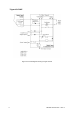
Triguard SC300E Figure 2-3 Circuit diagram showing a single channel 6 TDI16BIA October 2005 – Issue 3
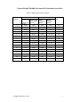
Triguard SC300E TDI16BIA 16-Channel D/I Termination Card 24Vdc EXTERNAL CONNECTIONS Fixed Terminal Details Field connector J2 Connector, 34-way, DIN41612, female Chassis connector J1 Connector, 34-way, DIN41612, female Field power supply inputs FS1 and FS2 Header, 2-way, Molex Minifit Jr Alarm output PL1 Header, 2-way, Molex KK Ground terminal TS1 Provision for M3 ring terminal THEORY OF OPERATION Figure 2-3 is a circuit diagram showing a typical digital input channel.
Triguard SC300E TRANSIENT SUPPRESSION A transient suppressor is fitted across each digital input channel input to the SC300E chassis. It provides a discharge path for transient energy pulses that may appear on the digital input line following lightning strikes etc. The suppressor is effectively a zener diode with a breakdown voltage just above that of the normal supply voltage. In normal operation, therefore, the suppressor does not conduct (apart from leakage current).
Triguard SC300E TDI16BIA 16-Channel D/I Termination Card 24Vdc Table 2-2.
Triguard SC300E SERVICING SCOPE The TDI16BIA contains all-passive circuitry that is extremely robust. Servicing operations will therefore not normally extend beyond the replacement of failed fuses. CAUTION Before replacing a failed fuse, ascertain the cause of failure, and take the appropriate remedial action. CONFIGURATION No configurable links.
Triguard SC300E TDI16BIA 16-Channel D/I Termination Card 24Vdc SERVICE SUPPORT SPARE PARTS Spare parts and technical advice can be obtained from your local area offices. LIST OF SPARES Circuit Ref. F1 to F16 12 Part No.