
Manual

8
TAI16AI
A
October
200
5
–
Issue 3
Triguard
SC300E
TRANSIENT
SUPPRESSIO
N
A transient
suppressor
is
fitted
across
each
digital
input
channel
input
to
the
SC300E
chassis.
It
provides
a discharge
path
for
transient
energy
pulses
that
may
appear
on
the
digital
input
line
following
lightning
strikes
etc.
The
suppressor
is
effectively
a zener
diode
with
a breakdown
voltage
just
above
that
of
the
normal
supply
voltage.
In
normal
operation,
therefor
e,
the
suppressor
does
not
conduct
(apart
from
leakage
current).
In
the
presence
of
a transient
pulse,
zener
breakdown
occurs.
The
voltage
developed
across
the
suppressor
varies
to
some
extent
with
the
pulse
current
and
is
known
as
the
‘clamping’
voltage.
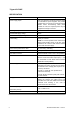
The
following
characteristics
are
typical:
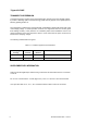
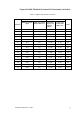
Table
2
-
1.
Transient
suppressor
characteristics
Clamping
Voltage
Pulse
currents
Pulse
duration
Comments
+37V
to
+43V
*1mA
Continuous
*Maximum
current
continuous
overload
+70V
**6gAmps
8
to
20
s
**Maximum
peak
pulse
current
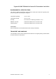
SUPPLEMENTARY INFORM
ATION
Table
2
-
2 lists
the
digital
input
channel
wiring
connections
and
associated
fuses
for
connectors
J1
and
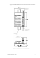
J2.
Pin
J1
-
1a
is
connected
to
the
+ve
bus
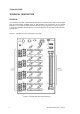
(Figure
2
-
3 ).
Pins
J1
-
1c
and
J2
-
1c
are
interconnected.
J1/J2
pins
other
than
J1
-
1a,
J1
-
1c,
J2
-
1c
and
those
listed
in
Table
2
-
2 are
not
connected.