
Owner manual


Wiring the Drive
4-1
CHAPTER 4
Wiring the Drive
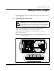
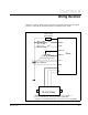
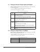
Figure 4.1 shows the wiring scheme for the drive’s external control inputs and outputs.
Sections 4.1 through 4.3 provide information for wiring the drive circuits.
Figure 4.1 – Drive External Wiring Diagram
Drive
FAULT
ON/OFF
HI/LO
POT1 (+)*
POT2 (-)*
+28 V
GND
U
V
W
T1 T2 T3
20 VAC Motor
3
Drive
Lamp or Relay
(500 mA max.)
Open = OFF
Closed = ON
Open = HI
Closed = LO
3
2
1
1K Potentiometer or
External Voltage Source
1
28 Volt Battery
+
–
1
When using 0 to 4.5 VDC external voltage source, POT1 is +.
2
Fuse or circuit breaker, value dependent on application.
3
Contact your local Reliance Electric sales office for motor availability.
2