TD200 AC Drive Installation and Operation Manual Version 1.0 0.
The information in this manual is subject to change without notice. Throughout this manual, the following notes are used to alert you to safety considerations: ! ATTENTION: Identifies information about practices or circumstances that can lead to personal injury or death, property damage, or economic loss. Important: Identifies information that is critical for successful application and understanding of the product.
CONTENTS Chapter 1 Introduction to the Drive 1.1 Drive Description ............................................................................................. 1-1 1.2 Identifying the Drive by Model Number ........................................................... 1-1 1.3 Getting Assistance from Reliance Electric....................................................... 1-1 Chapter 2 Setting the Drive Jumpers 2.1 Removing the Drive Cover ....................................................................
II TD200 AC Drive Installation and Operation
LIst of Figures Figure 1.1 – Identifying the Drive Model Number ..................................................... 1-1 Figure 2.1 – Location of Drive Jumpers.................................................................... 2-1 Figure 2.2 – V/Hz Curve ........................................................................................... 2-3 Figure 3.1 – Drive Mounting Dimensions.................................................................. 3-1 Figure 4.1 – Drive External Wiring Diagram .......
IV TD200 AC Drive Installation and Operation
List of Tables Table 2.1 – Maximum Speed Jumper Settings......................................................... 2-2 Table 2.2 – V/Hz Curve Jumper Settings ................................................................. 2-3 Table 2.3 – Current Rating Jumper Settings ............................................................ 2-4 Table 2.4 – External Speed Control Jumper Settings............................................... 2-5 Table 2.
VI TD200 AC Drive Installation and Operation
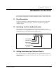
CHAPTER 1 Introduction to the Drive This chapter describes the drive and how to identify it using the model number matrix. It also provides an illustration of the drive showing the locations of major components. 1.1 Drive Description The drive is powered by a nominal +28 VDC input, and provides a three-phase AC variable frequency and voltage output to control a 63 amp AC motor (maximum continuous amps). 1.2 Identifying the Drive by Model Number Each 2 HP AC drive can be identified by its model number.
1-2 TD200 AC Drive Installation and Operation
CHAPTER 2 Setting the Drive Jumpers Before the drive can be mounted and wired, you must set the drive jumpers to match your drive application. 2.1 Removing the Drive Cover ! ATTENTION: This drive contains ESD (Electrostatic Discharge) sensitive parts and assemblies. Static control precautions are required when installing, testing, servicing or repairing this assembly. Component damage may result if ESD control procedures are not followed.
2.2 Setting the Speed Reference Jumper (J1) Jumper J1 is used to select between the external speed reference or the internal speed jumpers. When this jumper is set (J1 = 1), the motor speed can be externally adjusted from the POT1 and POT2 terminals (see section 2.6). When J1 is reset (J1 = 0), the internal speed jumpers (J2 through J8 ) are used to set the maximum speed. In either configuration, the "HI/LO" external input is active (see section 4.1).
2.4 Setting the V/Hz Curve Jumpers (J9 through J12) Jumpers J9 through J12 set the frequency break point for the V/Hz Curve . The breakpoint is the frequency at which the output voltage reaches the maximum voltage. Below this point the output voltage and frequency increase together. This feature is required to allow the drive to work with motors rated at various frequencies. Figure 2.2 shows a general V/Hz curve. V Vmax Boost F (Hz) Figure 2.2 – V/Hz Curve Table 2.
2.5 Setting the Current Rating Jumpers (J13 through J16) Jumpers J13 through J16 set the maximum continuous current rating and the associated current limit level of the drive’s output current. The four jumpers are binary weighted and scaled so that the current limit level is adjustable from 30 to 70 amps RMS in approximate 3 amp RMS steps. Table 2.3.6 shows the nominal current limit level for each possible jumper setting. Table 2.
2.6 Setting the External Speed Control Jumpers (J17 through J19) The motor speed can be manually adjusted between minimum speed and full speed with 0 to 4.5 volt voltage reference, or a 1000 ohm potentiometer. To make the external speed control inputs (POT1, POT2) active, jumper J1 (Speed Reference Jumper) must be in the Speed Ref position (J1 = 1), as described in section 2.2. Jumpers J17 through J19 configure the external speed control function for either an external 1 Kohm pot control or a 0 to 4.
2.7 Reattaching the Cover Follow these steps to reattach the drive cover. Step 1. Position the cover on the back of the drive. Step 2. Reinstall the six M4 machine screws finger tight, beginning with the two middle screws, then the four corner screws. Step 3. Beginning with the two middle screws, torque all of the screws to 4 to 6 lb-in ( .45 to .68 Nm). Do not overtighten.
CHAPTER 3 Mounting the Drive 3.1 Planning the Installation The drive should be installed in a location where high airflow and low ambient temperatures are present. The jumpers must be configured before installation, because their access is from the bottom of the unit. 3.2 Mounting the Drive Use the following steps to mount the drive. Step 1. Prepare the mounting surface based on the dimensions shown in figure 3.1. Step 2. Position the drive in the enclosure.
3-2 TD200 AC Drive Installation and Operation
CHAPTER 4 Wiring the Drive Figure 4.1 shows the wiring scheme for the drive’s external control inputs and outputs. Sections 4.1 through 4.3 provide information for wiring the drive circuits. Lamp or Relay (500 mA max.) FAULT Open = OFF Closed = ON ON/OFF Open = HI Closed = LO HI/LO 2 POT1 (+)* 3 1K Potentiometer or External Voltage Source1 2 + Drive Drive 1 POT2 (-)* +28 V 28 Volt Battery – GND U V W T1 T2 T3 20 VAC Motor 3 1 When using 0 to 4.5 VDC external voltage source, POT1 is +.
4.1 Wiring the External Control Inputs and Outputs Table 4.1 describes the external control circuits shown in figure 4.1. All control circuits should be wired as follows: • use 12 to 18 AWG wire terminated with ring lugs sized for a #8 stud. • torque all connections between 11 to 13 in-lb. Table 4.1 – External Control Inputs and Ouputs Terminal Label Function ON/OFF ON = Closed to run motor OFF = Open to stop motor There is an approximate delay of 1.0 second at startup. Peak input current = 0.
4.3 Wiring Input Power to the Drive ! ATTENTION: The input power of this drive is not internally fused. The user is responsible for external fusing. Failure to observe this precaution could result in damage to, or destruction of, the equipment. ATTENTION: Applying reverse polarity at the drive input terminals will allow unlimited input current to flow. A user-supplied fast-acting fuse or circuit breaker should be installed in the drive input circuit to prevent damage to the drive.
4-4 TD200 AC Drive Installation and Operation
CHAPTER 5 Checking the Installation ! ATTENTION: Only qualified electrical personnel, familiar with the construction and operation of this equipment and the hazards involved, should install, adjust, operate, and/or service this equipment. Read and understand this manual in its entirety before proceeding. Failure to observe this precaution could result in severe bodily injury or loss of life. To ensure safe operation, check the installation with the power off before operating the unit.
Step 5. Visually check the direction of motor shaft rotation. If shaft rotation is correct, proceed to the next section, Testing the Drive under Load. If shaft rotation is incorrect, continue to step 7. Step 6. Disconnect DC input power to the unit. Step 7. Reverse any two of the three motor power leads (U, V, and W). 5.3 Testing the Drive under Load Use the following procedure to test the drive under load: Step 1. Turn off, lockout, and tag power to the drive. Step 2.
CHAPTER 6 Operating the Drive The following table describes how to start and stop the drive, and how to change the motor speed. This table assumes that the drive is wired as shown in figure 4.1. Table 6.1 – Operating the Drive Function Process Start the drive Apply 28 VDC to the ON/OFF terminal. Stop the drive Remove 28 VDC to the ON/OFF terminal. Adjust motor speed Motor speed can be controlled by: • jumper settings (see section 2.3). • speed potentiometer (see section 2.6).
6-2 TD200 AC Drive Installation and Operation
CHAPTER 7 Diagnostics and Troubleshooting 7.1 Drive Faults and Corrective Actions The drive has two status LEDs that can be used to diagnose drive faults. Table 7.1 lists some possible drive faults and their corrective actions. Table 7.1 – Drive Status Indicators Motor LED (M) Drive LED (D) Drive is running ON ON Drive is running (normal status). Drive runs, but not at commanded speed ON ON Internal speed reference set improperly Check jumper settings (J1 - J8).
7-2 TD200 AC Drive Installation and Operation
APPENDIX A Technical Specifications Drive Dimensions Height: 12.95 inches Width: 6.50 inches Depth: 4.12 inches Weight: 7.88 pounds Input Voltage Nominal: +28 VDC Operating Range: +20 to +32 VDC Maximum Non-operating Transient: +60 V peak., 0.1 seconds Source: battery, battery & alternator, stand-alone alternator, or DC power supply Note: Negative voltage should not be applied to the drive. Input Current Nominal: +65 A DC (@ 28 VDC input and rated HP) Output Voltage Nominal: 0.
Shock and Vibration Will withstand 3-axis sinusoidal vibration from 20 to 200 Hz @ 2 g. Will withstand 3-axis, 10 g shock pulse with a duration of 8 msec. Cooling Air Requirements Minimum air velocity: 1000 linear ft/min (LFM) referenced to standard conditions of 25° C and 760 mm Hg, directed through base areas of the unit’s cooling fins. Electromagnetic Interference (EMI) This product has been tested for immunity to electrostatic discharges, radiated interference, and electrical fast transients.
U.S. Drives Technical Support Tel: (1) 262.512.8176, Fax: (1) 262.512.2222, Email: support@drives.ra.rockwell.com, Online: www.ab.com/support/abdrives Trademarks not belonging to Rockwell Automation are property of their respective companies. Publication D2-3462- October 2000 Copyright © 2000 Rockwell Automation, Inc. All Rights Reserved. Printed in USA.