
Manual


Trusted
TM
Power Distribution Unit MCB 24Vdc T8292
Issue 8 Nov 08 4
Table of Contents
1. Description......................................................................................................................................7
2. Status Indicators.............................................................................................................................8
3. Configuration ..................................................................................................................................9
3.1. Option 1 .......................................................................................................................................9
3.2. Option 2 .....................................................................................................................................10
3.3. Option 3 .....................................................................................................................................11
3.4. Option 4 .....................................................................................................................................12
4. Installation ....................................................................................................................................13
5. Associated Cable Selection..........................................................................................................13
6. Terminal Connections ..................................................................................................................14
7. Specifications ...............................................................................................................................15
Figures
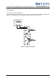
Figure 1 T8292 Photo ...............................................................................................................................3
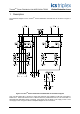
Figure 2 Trusted
T
M
Power Distribution Unit MCB 24V dc Schematic Diagram.........................................7
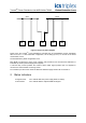
Figure 3 Single line power diagram ..........................................................................................................8
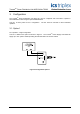
Figure 4 Configuration Option 1................................................................................................................9
Figure 5 Configuration Option 2..............................................................................................................10
Figure 6 Configuration Option 3..............................................................................................................11
Figure 7 Configuration Option 4..............................................................................................................12
Tabl es
Table 1 Associated Cable Selection .......................................................................................................13
Table 2 Terminal Connections................................................................................................................14