
Manual

Trusted
TM
Communication Interface T8151B
Issue 21 Apr 10 PD-T8151B 32
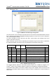
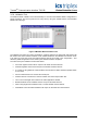
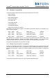
3.5.7. Messages Tab
Figure 12 Modbus Slave Message Configuration
This panel lists all of the messages for the slave device in the order that the Modbus Master executes
them. Dragging and dropping a highlighted message anywhere in the list can be used to change the
order of the messages in the list.
To create a message to send to this slave, click ‘New’. (‘Insert’ adds a new message at the cursor
position, ‘New’ adds at the end).
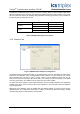
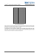
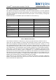
Select a Message Type from the list. Depending on the address range and the number of addresses,
the appropriate Modbus command is used. The supported commands are shown below..
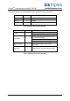
Address Range Size Direction Modbus Command
Low High Type Code
1 9999 1 Read Read Coil Status (Read Coils) 0x01
1 9999 1 Write Force single Coil (Write Coils) 0x05
1 9999 2 - 512 Read Read Coil Status (Read Coils) 0x01
1 9999 2 - 512 Write Force Multiple Coils (Write Coils) 0x15
10001 19999 1 - 512 Read Read Input Status (Read Inputs) 0x02
30001 39999 1- 125 Read Read Analogue Inputs (Read IP Registers) 0x04
40001 49999 1 - 125 Read Read Holding register (Read Registers) 0x03
40001 49999 1 Write Preset Single Register (Write Registers) 0x06
40001 49999 2 - 123 Write Preset Multiple Registers (Write Registers) 0x16
Table 11 Modbus Message Types
The Variable Network Address is the Modbus address range of the variables as mapped in the
Trusted
TM
system. Only the starting address is needed; the end address is calculated automatically.
The Modbus Slave Address is the slave’s address range for the variables. Enter the start and end
addresses. The available address ranges and maximum number of addresses in a single message are
shown above.