
Manual

Trusted
TM
Communication Interface T8151B
Issue 21 Apr 10 PD-T8151B 14
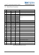
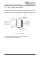
2.3. Module Pinout Connections
Row
Pin A B C Description
1
2
50
Co-ax
10Base2 Ethernet 1
(fitted on T8151 up to build H and T8151B up to build B only)
3
4 Link 1 Connector Present Link - wire to A29
5 TXD1 (RS232)
Serial Port 1
6 RTS1 (RS232) DTR1 (RS232) RXD1 (RS232)
7 CTS1 (RS232) DSR1 (RS232) DCD1 (RS232)
8 BIO1 (RS485) AIO1 (RS485) RI1 (RS232)
9 BO1 (RS485) AO1 (RS485) GND1
10
11 TXD2 (RS232) RTS2 (RS232) RXD2 (RS232) Serial Port 2
12 BIO2 (RS485) AIO2 (RS485) CTS2 (RS232)
13 BO2 (RS485) AO2 (RS485) GND2
14
15 BIO3 (RS485) AIO3 (RS485) GND3
Serial Port 3
16 BO3 (RS485) AO3 (RS485) GND3
17
18 BIO4 (RS485) AIO4 (RS485) GND4
Serial Port 4
19 BO4 (RS485) AO4 (RS485) GND4
20
21 TD+1 TD-1
10/100BaseT Ethernet 1
22 RD+1 RD-1
23 EARTH1
24
25 TD+2 TD-2
10/100BaseT Ethernet 2
26 RD+2 RD-2
27 EARTH2
28
29 LINK2 Connector Present Link - wire to C4
30
31
50
Co-ax
10Base2 Ethernet 2
(fitted on T8151 up to build H and T8151B up to build B only)
32
Table 3 External I/O Connector - Pin Out