
Manual

Trusted
TM
120Vac Digital Output FTA T8871
Issue 2 Feb 08 PD-T8871 4
Table of Contents
1. Description...................................................................................................................................7
2. Installation....................................................................................................................................8
3. Associated Cable Selection .........................................................................................................8
4. Assembly Pinout Connections .....................................................................................................9
4.1. SK1 Connections from module....................................................................................................9
4.2. SK3 Connections from module....................................................................................................9
4.3. SK2 Power connection to module..............................................................................................10
4.4. SK4 Power connection to module..............................................................................................10
4.5. TB1 Field Connections...............................................................................................................11
4.6. TB3 Field Connections...............................................................................................................11
4.7. TB2 Power supply connection ...................................................................................................12
4.8. TB4 Power supply connection ...................................................................................................12
5. Specifications.............................................................................................................................13
Figures
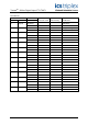
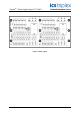
Figure 1 T8871 Layout..............................................................................................................................3
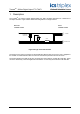
Figure 2 Single Channel Schematic .........................................................................................................7
Figure 3 TB1 and TB3 Connections (example) ......................................................................................11
Tab l e s
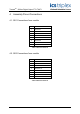
Table 1 SK1 Connections .........................................................................................................................9
Table 2 SK3 Connections .........................................................................................................................9
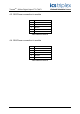
Table 3 SK2 Connections .......................................................................................................................10
Table 4 SK4 Connections .......................................................................................................................10
Table 5 TB1 Connections .......................................................................................................................11
Table 6 TB3 Connections .......................................................................................................................11
Table 7 TB2 Connections .......................................................................................................................12
Table 8 TB4 Connections .......................................................................................................................12