
User Manual


Trusted
TM
Versatile FTA T8842
Issue 8 Aug 12 PD-T8842 4
Table of Contents
1. Description ................................................................................................................................... 8
1.1. Digital Inputs (Powered) ............................................................................................................. 10
1.2. Digital Inputs (Line Monitored) ................................................................................................... 11
1.3. Digital Output ............................................................................................................................. 12
1.4. Analogue inputs (4-20mA) ......................................................................................................... 13
1.5. Fire Input Loops ......................................................................................................................... 14
1.6. Monitored Valve Outputs ........................................................................................................... 15
2. Installation .................................................................................................................................. 16
3. Associated Cable Selection ....................................................................................................... 16
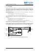
4. Assembly Pinout Connections ................................................................................................... 16
4.1. TBFP1 to TBFP5 Connections .................................................................................................. 17
4.2. TBG1 Connections .................................................................................................................... 17
4.3. TBG2 Connections .................................................................................................................... 18
4.4. TBG3 Connections .................................................................................................................... 18
4.5. TBG4 Connections .................................................................................................................... 19
4.6. TBG5 Connections .................................................................................................................... 19
4.7. TBSS Connections..................................................................................................................... 20
4.8. TB1 to TB40 Connections .......................................................................................................... 20
4.9. Links........................................................................................................................................... 21
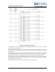
5. Specifications ............................................................................................................................. 22