TrustedTM PD-T8841 TrustedTM 8 Channel RTD FTA Introduction TM TM The Trusted 8 Channel RTD FTA T8841 provides an interface between a Trusted System and up to eight Platinum 100R RTD sensors which may be connected using two or 3-wire configurations. Each RTD FTA channel may be configured to provide either a scaled current output in the range of 4-20mA, or a scaled voltage output in the range of 1-5V dc. The RTD FTA also provides sensor excitation and linearisation for each channels.
TrustedTM RTD FTA T8841 Issue Record Issue Number Date Revised by 5 Sep 05 J W Clark 6 Nov 07 N Owens Issue 6 Nov 07 Technical Check Authorised by Modification Format A Holgate PD-T8841 P Stock Cable advice 2
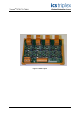
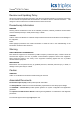
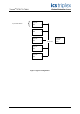
TrustedTM RTD FTA T8841 Figure 1 T8841 Layout Issue 6 Nov 07 PD-T8841 3
TrustedTM RTD FTA T8841 Table of Contents 1. Description ...................................................................................................................................7 2. System Functions ........................................................................................................................8 2.1. Zero, Gain & Linearisation ...........................................................................................................8 3. Installation................
TrustedTM RTD FTA T8841 Notice The content of this document is confidential to ICS Triplex Technology Ltd. companies and their partners. It may not be given away, lent, resold, hired out or made available to a third party for any purpose without the written consent of ICS Triplex Technology Ltd. This document contains proprietary information that is protected by copyright. All rights are reserved.
TrustedTM RTD FTA T8841 Revision and Updating Policy All new and revised information pertinent to this document shall be issued by ICS Triplex Technology Ltd. and shall be incorporated into this document in accordance with the enclosed instructions. The change is to be recorded on the Amendment Record of this document.
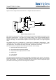
TrustedTM RTD FTA T8841 1. Description Figure 2 shows a single channel of the RTD FTA. All eight channels are identical. Figure 2 Single Channel Circuit Each channel of the RTD FTA contains a precision RTD instrumentation amplifier circuit based on the Burr Brown XTR105 device. The device is a monolithic 4-20mA, 2-wire current transmitter with two precision current sources.
TrustedTM RTD FTA T8841 Each RFTA temperature output is configurable for the following: 1. 4-20mA current source output. 2. 0-5V dc voltage source output. The 4-20mA current source output is the preferred option. The 0-5V dc option provides an overall operating range of 0-5V dc with a healthy field loop operating range of 1-5V dc. RTD devices in the field are connected to the RTD FTA by cables terminated at eight 3-way connectors (RTD1 to RTD8).
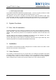
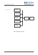
TrustedTM RTD FTA T8841 RTD FTA Up to 8 RTD devices 8841 RTD FTA 8841 RTD FTA Analogue module 8841 TC-211/212 8431 RTD FTA 8841 RTD FTA 8841 Figure 3 Typical configuration Issue 6 Nov 07 PD-T8841 9
TrustedTM RTD FTA T8841 RTD FTA 8841 Up to 8 RTD devices Or separate inputs RTD FTA 8841 Or separate inputs RTD FTA 8841 Or separate inputs VFTA 8842 Analogue module 8431 RTD FTA 8841 Or separate inputs RTD FTA 8841 Or separate inputs Figure 4 Configuration using VFTA Issue 6 Nov 07 PD-T8841 10
TrustedTM RTD FTA T8841 4. Assembly Pinout Connections 4.1. RTD1 to RTD8 RTD Sensor Cable Colour Pin Service 2-Wire 3-Wire 1 (W) + Input White White 2 (R) + Input Red Red 3 (R) I Return Red Table 1 RTD Connections 4.2.
TrustedTM RTD FTA T8841 5. Link Assignments The functions of the links are detailed below. 5.1. Two Wire Operation The links listed in the table below must be fitted for 2-wire operation. The RTD FTA defaults to 3-wire operation if the links detailed are not fitted. Channel Link 1 LK93 2 LK89 3 LK94 4 LK90 5 LK95 6 LK91 7 LK96 8 LK92 Table 4 Two Wire Link Assignments 5.2. Voltage Output The links listed in the table below must be fitted for voltage output.
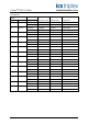
TrustedTM RTD FTA T8841 5.3. Measurement range 0 to 1000C The links listed in the table below must be fitted to enable the RTD FTA to measure temperatures in 0 the range 0 to 100 C. Channel Link 1 LK5, LK6, LK21, LK29, LK31, 2 LK49, LK50, LK65, LK73 LK75, 3 LK9, LK10, LK23, LK33, LK35 4 LK53, LK54, LK67, LK77, LK79 5 LK13, LK14, LK25, LK37, LK39 6 LK57, LK58, LK69, LK81, LK83 7 LK17, LK18, LK27, LK41, LK43 8 LK61, LK62, LK71, LK85, LK87 Table 6 Range 0 to 100 deg C Link Assignments 5.4.
TrustedTM RTD FTA T8841 6. Specifications Number of Inputs 8 Channels (2 or 3-wire) Voltage Range 20 to 32V dc Power Isolation ±250V dc Power Consumption (per channel @24V dc) 60 to 720mW Sensor Excitation Current 0.
TrustedTM RTD FTA T8841 This page is intentionally blank Issue 6 Nov 07 PD-T8841 15