
Manual


Trusted
TM
AI/DI FTA External Power T8834
Issue 2 Aug 06 PD-T8834 4
Table of Contents
1. Description...................................................................................................................................7
2. Installation....................................................................................................................................8
3. Associated Cable Selection .........................................................................................................8
4. Assembly Pinout Connections .....................................................................................................9
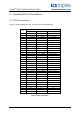
4.1. CON1 Connections ......................................................................................................................9
4.2. TB1 Connections .......................................................................................................................10
4.3. TB2 Connections .......................................................................................................................11
4.4. TB3 Connections .......................................................................................................................12
5. Field Circuit Design....................................................................................................................13
6. Specifications.............................................................................................................................16
Figures
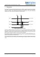
Figure 1 Single Channel Schematic .........................................................................................................7
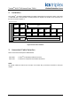
Figure 2 Connector locations....................................................................................................................8
Figure 3 2-20mA, 2 wire, Field Sourcing Current ...................................................................................13
Figure 4 0-20mA, 2 Wire, Field Sourcing Current ..................................................................................14
Figure 5 0-20mA, 3 Wire, Field Sinking Current.....................................................................................14
Figure 6 FTA Circuit Diagram.................................................................................................................15
Tab l e s
Table 1 CON1 Connections......................................................................................................................9
Table 2 TB1 Connections .......................................................................................................................10
Table 3 TB2 Connections .......................................................................................................................11
Table 4 TB3 Connections .......................................................................................................................12