TrustedTM PD-T8451 TrustedTM TMR 24Vdc Digital Output Module – 40 Channel Introduction TM The Trusted TMR 24V dc Digital Output module interfaces to 40 field devices. Triplicated diagnostic tests are performed throughout the module including measurements for current, and voltage on each portion of the voted output channel. Tests are also performed for stuck on and stuck off failures.
TrustedTM Module T8451 Issue Record Issue Number Date Revised by 8 July 05 J W Clark Technical Check Authorised by Modification Reformat Text Editing 9 Aug 06 N Owens I Vince P Stock Channel States 10 Dec 06 V Middleton N Owens P Stock Weights & Dims 11 Nov 07 N Owens A Holgate P Stock STATE descriptions 12 Apr 10 S Blackett A Holgate N Owens Rack 7 table minor change Issue 12 Apr 10 PD-T8451 2
TrustedTM Module T8451 This page is intentionally blank Issue 12 Apr 10 PD-T8451 3
TrustedTM Module T8451 Table of Contents 1. Description......................................................................................................................................8 1.1. Field Termination Unit (FTU)..........................................................................................................9 1.2. Field Interface Unit (FIU) ................................................................................................................9 1.3.
TrustedTM Module T8451 5.1. Fault Reporting .............................................................................................................................28 5.2. Field Wiring Faults........................................................................................................................28 5.3. Module Faults ...............................................................................................................................28 5.4. Companion Slot .................
TrustedTM Module T8451 Notice The content of this document is confidential to ICS Triplex Technology Ltd. companies and their partners. It may not be given away, lent, resold, hired out or made available to a third party for any purpose without the written consent of ICS Triplex Technology Ltd. This document contains proprietary information that is protected by copyright. All rights are reserved.
TrustedTM Module T8451 Precautionary Information WARNING Warning notices call attention to the use of materials, processes, methods, procedures or limits which must be followed precisely to avoid personal injury or death. CAUTION Caution notices call attention to methods and procedures which must be followed to avoid damage to the equipment.
TrustedTM Module T8451 1. Description TM The TMR 24V dc Digital Output module is a member of the Trusted range of Input/Output (I/O) TM modules. All Trusted I/O modules share common functionality and form. At the most general level, all I/O modules interface to the Inter-Module Bus (IMB) which provides power and allows communication with the TMR Processor. In addition, all modules have a field interface that is used to connect to module specific signals in the field.
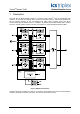
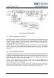
TrustedTM Module T8451 TM Fig 2 shows a simplified block diagram of the Trusted 24V dc Digital Output module. Figure 2 Functional Block Diagram 1.1. Field Termination Unit (FTU) The Field Termination Unit (FTU) is the section of the I/O module that connects all three FIUs to a single field interface. The FTU provides the Group Fail-safe switches and passive components necessary for signal conditioning, over-voltage protection, and EMI/RFI filtering.
TrustedTM Module T8451 1.3. Host Interface Unit (HIU) The HIU is the point of access to the Inter-Module Bus (IMB) for the module. It also provides power distribution and local programmable processing power. The HIU is the only section of the I/O module to directly connect to the IMB backplane. The HIU is common to most high integrity I/O types and has type dependent and product range common functions. Each HIU contains three independent slices, commonly referred to as A, B, and C.
TrustedTM Module T8451 1.5. Line monitoring and output states The module automatically monitors the output channel current and voltage to determine the state of the output channel. The numerical output state and line fault status are reported back to the application and are represented below.
TrustedTM Module T8451 The power supplies for both the HIU and FIU boards are redundant, fully instrumented and testable. Together these assemblies form a Power Integrity Sub System. 1.8. Sequence of Events Characteristics The module automatically measures the field voltage and current to determine the state of each output channel. An event occurs when the output transitions from one state to another. When a channel changes state, the on-board timer value is recorded.
TrustedTM Module T8451 The reason that the lower switches are specified to be on in the absence of control signal power is to allow two channels to power the load should an entire slice fail. Even if an entire slice fails, the surviving output circuits will carry the necessary control. The structure of each OFIU output is shown below: Figure 4 Simplified Switch Circuit Diagram A resistor provides a means of continuously monitoring the switch current.
TrustedTM Module T8451 1.9.2. Short Circuit Protection Issues TM In a fuse-free design such as in the Trusted System, the module is required to respond rapidly in the event of an over-current or over-power situation. In fact, this protection scheme offers advantages to fuses in both automatic recovery and speed of action. The topology of the channel provides a natural limit to the instantaneous current flow, giving the module time to respond.
TrustedTM Module T8451 2. Installation 2.1. Module Insertion/Removal CAUTION: The module contains static sensitive parts. static handling precautions must be observed. Specifically ensure that exposed connector pins ARE NOT TOUCHED. Under no circumstances should the module housing BE REMOVED. Before installation, visually inspect the module for damage. Ensure that the module housing appears undamaged and inspect the I/O connector at the back of the module for bent pins.
TrustedTM Module T8451 2.4.
TrustedTM Module T8451 2.5. TrustedTM Module Polarisation/keying. TM All Trusted Modules have been Keyed to prevent insertion into the wrong position within a chassis. The polarisation comprises two parts. The module and the associated field cable. Each module type has been keyed during manufacture.
TrustedTM Module T8451 3. Application 3.1. Module Configuration There is no configuration required to the physical output module. All configurable characteristics of the module are performed using tools on the EWS and become part of the application or system.ini file that is loaded into the TMR Processor. The TMR Processor automatically configures the output module after applications are downloaded and during Active/Standby changeover.
TrustedTM Module T8451 OEM Parameter Description Notes TICS_CHASSIS The number of the TM Trusted Chassis where the primary I/O module is installed The Trusted Controller Chassis is 1, and TM Trusted Expander Chassis are 2 to 15 TICS_SLOT The slot number in the chassis where the primary I/O module is installed The I/O module slots in the Trusted Controller chassis are numbered from 1 to 8.
TrustedTM Module T8451 Value Description 7 Channel fault 6 Field fault (e.g. field leakage to 0V or 24V) 5 Short circuit in field wiring or load 4 Output energised (ON) 3 Open circuit in field wiring or load 2 Output de-energised (OFF) 1 No field supply voltage 0 Unused Table 7 Rack 2: STATE Output description 3.2.3. Rack 3: AI The AI board returns the field loop voltage at the output.
TrustedTM Module T8451 3.2.4. Rack 4: CI The CI board returns the field loop current at the output. Channel Description 1 Field output channel 1 current 2 Field output channel 2 current 40 Field output channel 40 current Table 9 Rack 4: CI descriptions The current is the sum value taken from the triplicated module. The current level is reported as an 1 integer, with the units being /1000A. This may be used directly, scaled arithmetically or scaled using the IEC1131 TOOLSET conversion tables.
TrustedTM Module T8451 3.2.7.
TrustedTM Module T8451 Each input within the housekeeping rack is reported as an integer. In general, the application engineer will not normally require these inputs. They are provided to aid fault finding and diagnosis and may be used for reporting and display purposes. If a slice is Fatal, then all reported housekeeping inputs are set to zero. 3.2.8.
TrustedTM Module T8451 The FCR Status channel reports the fault status of the active and standby modules.
TrustedTM Module T8451 4. Operation 4.1. Front Panel Status indicators on the front panel of the module provide visual indications of the module’s operational status and field output status. Each indicator is a bicolour LED. Located at the top and bottom of each module is an ejector lever that is used to remove the module from the chassis. Limit switches detect the open/closed position of the ejector levers.
TrustedTM Module T8451 4.2. Module Status LEDs There are six module status indicators on the module front panel: three Healthy, one Active, one Standby, and one Educated. The Healthy indicators are controlled directly by each module slice. The Active, Standby, and Educated indicators are controlled by the FPU. The FPU receives data from each of the module slices. The FPU performs a 2-oo-3 vote on each data bit from the slices and sets the indicators accordingly.
TrustedTM Module T8451 4.3. I/O Status Indicators There are 40 output channel status indicators on the module front panel, one for each field output. These indicators are controlled by the FPU. The FPU receives data from each of the module slices. The FPU performs a 2-oo-3 vote on each data bit from the slices and sets the indicators accordingly. The output status indicator mode is dependent upon the numerical state of the output channel.
TrustedTM Module T8451 5. Fault Finding and Maintenance 5.1. Fault Reporting Output module faults are reported to the user through visual indicators on the front panel of the module and through status variables which may be automatically monitored in the application programs and external system communications interfaces. There are generally two types of faults that must be remedied by the user: external wiring and module faults.
TrustedTM Module T8451 5.4. Companion Slot TM For a Companion Slot configuration, two adjacent slots in a Trusted Chassis are configured for the same Output module function. One slot is the primary slot and the other a unique secondary (or spare) TM slot. The two slots are joined at the rear of the Trusted Chassis with a double-wide I/O Interface Cable that connects both slots to common field wiring terminations.
TrustedTM Module T8451 5.7. Transfer between Active and Standby Modules The TMR Processor is responsible for managing a pair of I/O modules through an active/standby changeover. The following rules apply to active/standby changeovers, though the TMR Processor and not the I/O module enforce them: • The user must define the primary, and optionally the secondary, I/O module location for each I/O module pair.
TrustedTM Module T8451 6. Specifications System Supply Voltage Range 20 to 32Vdc Circuit Type Fault tolerant, fully triplicated with optional line monitoring Number of Outputs 40 Channels Independent Power Groups 5 each of 8 outputs Operational Output/Field Voltage Range 18 to 32V dc Output Voltage Measurement Range 0 to 32V dc Maximum Withstanding -1 to 40V dc Output Current Rating (Continuous) 2A per channel limited to 8A per power group Maximum capacitance Pre release 3.