
User guide

Trusted
TM
Module T8449
Issue 13 Apr 10 PD-T8449 39
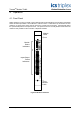
4.3. I/O Status Indicators
There are 40 channel status indicators on the module front panel, one for each control output and one
for each feedback channel. These indicators are controlled by the FPU. The FPU receives data from
each of the module slices. The FPU performs a 2-oo-3 vote on each data bit from the slices and sets
t
he indicators accordingly.
The control output status indicator mode is dependent upon the numerical state of the output channel.
Each control output state can be defined to have a particular indicator mode: off, green, red, flashing
green, or flashing red.
The feedback channel status indicator mode is dependent upon the numerical state of the feedback
channel which is derived by comparing the feedback channel voltage level to a set of thresholds. Each
feedback channel state can be defined to have a particular indicator mode: off, green, red, flashing
green, or flashing red.
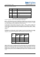
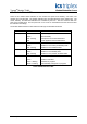
The configurable indicator modes allow users to customise the output status indications to suit
individual application requirements. Without customisation, the default control output indicator modes
are suitable for line-monitored digital output devices as described below:
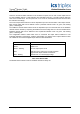
INDICATOR STATE DESCRIPTION
Off Output is Off.
Green Output is On.
Green – flashing No Load, output open circuit.
Red Field short circuit, output over current protection
triggered and output channel is latched off.
Red – flashing Channel fault, or no field supply voltage
Table 23 I/O Status LEDs
The default status indicator mode for feedback channels is always off.