
User guide

Trusted
TM
Module T8449
Issue 13 Apr 10 PD-T8449 34
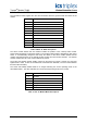
Valve Test State is used to report the state of the valve test that is in progress. Valve Test State is an
integer, with the following valid values:
Value State Description
0 Idle There is no valve test in progress.
1 Test In
Progress
A valve test is in progress.
2 Test Complete The valve test has completed (successfully).
3 Test Error There was an error and the valve test could
not start.
4 Test Aborted The valve test has been aborted.
5 Test Failure The valve test has failed.
Table 20 Rack 10: Valve Test State descriptions
The Valve Test State is reset to 0 on the falling edge of a TEST signal.
Time 1 … Time 5 are used to report the elapsed time (in milliseconds) from the start of the test until
the feedback input state changes to the corresponding state when the Valve Test State is not 0 (Idle)
or 4 (Test Aborted). (i.e. When the feedback input state changes from state 2 to state 3, the variable
Time 3 will be updated with the time elapsed since the start of the test.)
In cases where a state is entered more than once (i.e. state 1 -> state 2 -> state 3 -> state 2), the
corresponding Time variable will only be updated for the initial entry. If a feedback state is skipped, the
corresponding Time variable will assume the same value as the next valid state (i.e. state 4 -> state 2,
so Time 3 assumes the value of Time 2). If a Time variable has a value of 0, that state was not entered
during the test.
Example:
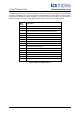
The field device is normally closed, normally energized valve with three limit switches: open, closed,
and partial. An end of line device is used to combine the output of the limit switches into a single
voltage level, and thresholds are established so that the feedback input states are as follows:
Limit Switch State
Feedback
Input
State
Valve is
Closed
Valve is
Partially
Open
Valve is
Open
5 TRUE FALSE FLASE
4 FALSE FLASE FLASE
3 FALSE TRUE FALSE
2 FALSE TRUE TRUE
1 Open Circuit Line Fault
Table 21 Rack 10: Example - Valve Position Feedback
When the valve is closed, the feedback input state should be reported as 5. A minimal partial stroke is
desired for the valve test, so we want the valve to move just enough to change the state of the Closed
limit switch. We set ETIME to be 200ms, and ESTATE to be 4. When the test is initiated, the normally
energized valve is de-energized. After 120ms the Feedback input state changes from 5 to 4. Since
ESTATE is also 4 and we have not exceeded the 200ms time limit set in ETIME, the test has
completed successfully. All of the Time variables will be 0 except for Time 4 which will have the value
of 120.