
User guide

Trusted
TM
Module T8449
Issue 13 Apr 10 PD-T8449 22
3. Application
3.1. Module Configuration
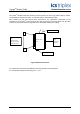
There is no configuration required to the physical output module. All configurable characteristics of the
module are performed using tools on the EWS and become part of the application or system.ini file
that is loaded into the TMR Processor. The TMR Processor automatically configures the output
module after applications are downloaded and during Active/Standby changeover.
The
IEC1131 TOOLSET provides the main interface to configure the output module. Details of the
configuration tools and configuration sequence is provided in PD-8082B. There are three procedures
necessary to configure the output module. These are:
1. Define the necessary I/O variables for the field output data and module status data using the
Dictionary Editor of the
IEC1131 TOOLSET.
2. Create an I/O module definition in the I/O Connection Editor for each I/O module. The I/O
module definition defines physical information, e.g. Chassis and Slot location, and allows
variables to be connected to the I/O channels of the module.
3. Using the Trusted
TM
System Configuration Manager, define custom LED indicator modes,
per-channel shutdown states, and other module settings.
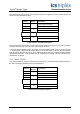
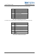
3.2. T8449 Complex Equipment Definition
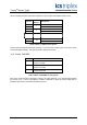
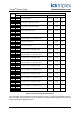
The T8449 I/O Complex Equipment Definition includes 8 I/O boards, referenced numerically by Rack
number:
Rack I/O Board Description
Data
Type
Direction
No. of
Channels
OEM Parameters - - -
1 DO_TEST
Output Command / Test Command Boolean Out 40
2 STATE Field Output State Integer In 40
3 AI _MXIN Output voltage / MUX data selection Integer In 40
4 CI _MXDAT Output current / MUX data Integer In 40
5 MXOUT MUX data request Integer Out 20
6 ETM_EST Max Test Time / Test End State Integer Out 40
7 LINEFLT Line Fault Status Boolean In 40
8 DISCREP Channel Discrepancy Integer In 3
9 HKEEPING Housekeeping Registers Integer In 57
10 INFO I/O Module Information Integer In 11
Table 3 Complex Equipment Definition