TrustedTM PD-T8449 TrustedTM TMR 24Vdc Valve Monitor Module - 40 Channel Introduction TM The Trusted TMR 24Vdc Valve Monitor module interfaces to 20 field devices. Each field device is controlled through an output channel, and monitored through a separate input channel. Triplicated diagnostic tests are performed throughout the module including measurements for current, and voltage on each portion of the voted output channel. Tests are also performed for stuck on and stuck off failures.
TrustedTM Module T8449 Issue Record Issue Number Date Revised by 6 July 05 John W Clark Technical Check Authorised by Modification Reformat.
TrustedTM Module T8449 Table of Contents 1. Description ................................................................................................................................8 1.1. Field Termination Unit (FTU).....................................................................................................9 1.2. Field Interface Unit (FIU) ...........................................................................................................9 1.3. Host Interface Unit (HIU)...........
TrustedTM Module T8449 3.2.10. Rack 10: INFO ........................................................................................................................31 3.2.11. Available MUX Channels.........................................................................................................32 3.3. Sequence of Events Configuration..........................................................................................35 3.4. SYSTEM.INI File Configuration...................................
TrustedTM Module T8449 Figures Figure 1 Module Architecture...................................................................................................................8 Figure 2 Functional Block Diagram .........................................................................................................9 Figure 3 Output Switch Structure...........................................................................................................12 Figure 4 Simplified Switch Circuit Diagram .........
TrustedTM Module T8449 Notice The content of this document is confidential to ICS Triplex Technology Ltd. companies and their partners. It may not be given away, lent, resold, hired out or made available to a third party for any purpose without the written consent of ICS Triplex Technology Ltd. This document contains proprietary information that is protected by copyright. All rights are reserved.
TrustedTM Module T8449 Revision and Updating Policy All new and revised information pertinent to this document shall be issued by ICS Triplex Technology Ltd. and shall be incorporated into this document in accordance with the enclosed instructions. The change is to be recorded on the Amendment Record of this document.
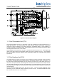
TrustedTM Module T8449 1. Description TM The TMR 24Vdc Valve Monitor module is a member of the Trusted High Integrity I/O Product Range. All High Integrity I/O modules share common functionality and form. At the most general level, all I/O modules interface to the Inter-Module Bus (IMB) which provides power and allows communication with the TMR Processor. In addition, all modules have a field interface that is used to connect to module specific signals in the field.
TrustedTM Module T8449 TM Fig 2 shows a simplified functional block diagram of the Trusted 24Vdc Valve Monitor Module. Figure 2 Functional Block Diagram 1.1. Field Termination Unit (FTU) The Field Termination Unit (FTU) is the section of the I/O module that connects all three FIUs to a single field interface. The FTU provides the Group Fail-safe switches and passive components necessary for signal conditioning, over-voltage protection, and EMI/RFI filtering.
TrustedTM Module T8449 The FIU also measures a range of on-board “house-keeping” signals that assist in monitoring the performance and operating conditions of the module. These signals include power supply voltages, current consumption, on-board reference voltages, and board temperature. 1.3. Host Interface Unit (HIU) The HIU is the point of access to the Inter-Module Bus (IMB) for the module. It also provides power distribution and local programmable processing power.
TrustedTM Module T8449 1.5. Line monitoring and output states The module automatically monitors the control output channel current and voltage to determine the state of the output channel. The numerical output state and line fault status reported back to the application is represented below.
TrustedTM Module T8449 Between the HIU and FIU are a series of optically isolated links for data and power. The data link is synchronised and monitored for variance. Both FIU and HIU have onboard temperature sensors to characterise temperature-related problems. The power supplies for both the HIU and FIU boards are redundant, fully instrumented and testable. 1.8.
TrustedTM Module T8449 absence of module power to create gate voltage signals to bias them on3 (unlike electromechanical relays for example). The reason that the lower switches are specified to be on in the absence of control signal power is to allow two channels to power the load should an entire slice fail. Even if an entire slice fails, the surviving output circuits will carry the necessary control. The structure of each OFIU output is shown below: Figure 4 Simplified Switch Circuit Diagram A 0.
TrustedTM Module T8449 1.9.1. Switch Diagnostics During normal operation, Switch 1 and Switch 2 are maintained on. In this state, Switch 1 and Switch 2 exhibit less than 0.5 ohms of resistance each. To determine the ability of the system to control the load via Switch 1 and Switch 2, their gate voltages are modulated, one at a time. As the gate voltages are modulated, the monitoring signals synchronously change in a predictable fashion.
TrustedTM Module T8449 used to control field devices. The remaining 20 channels always remain de-energized and are used to monitor feedback taking advantage of the channels built-in voltage measurement capability. Throughout this document, the 20 channels used to control field devices will be referred to as “control outputs”. The remaining 20 channels used to monitor feedback will be referred to as “feedback inputs”. Each control output is paired with a feedback input.
TrustedTM Module T8449 1.11.3. Test Operation Valve testing is initiated by sending the TEST signal from the user application to the module. Each signal will initiate a valve test on a per-channel basis (i.e. the application could send the TEST signal to all channels, several channels, or a single channel at any given time). A valve test consists of changing the state of the valve (i.e. from Energized/On to De-energized/Off or vice-versa) and monitoring the positional feedback.
TrustedTM Module T8449 Write the desired end state to the ESTATE signal. Turn the TEST signal off (logic ‘0’). This will clear the results of the previous test (if any). The Valve Test State will be reported as 0 (Idle). All other valve test variables (such as the Test Times, Sampled ETIME, and Sampled ESTATE) will be cleared to 0. Write 0 (Valve Test State) to the MXOUT signal. Wait for the MXIN value to be 0 (Valve Test State). MXDAT should now contain the Valve Test State which should be 0 (Idle).
TrustedTM Module T8449 2. Installation TM The output module always resides in the allocated I/O module slot (position) within the Trusted Controller or Expander Chassis. These module positions are keyed for T8449 modules to prevent installation of the incorrect module type. Other module positions are keyed to match their intended module type. The output module must NOT be installed in other module locations, as this may cause damage to the module. 2.1.
TrustedTM Module T8449 2.2. Field Termination Assembly (FTA) Selection TM I/O cables suitable for use with the Trusted Product Descriptions: TMR 24Vdc Valve Monitor are detailed in the following TM I/O Companion Slot Cables TM I/O SmartSlot Cables 1. PD-TC200 – Trusted 2. PD-TC500 – Trusted The Product Descriptions detailed above also detail the types of Field Termination Assembly (FTA) or Versatile Field termination Assembly (VFTA) which may be used with each type of module. 2.3.
TrustedTM Module T8449 2.4.
TrustedTM Module T8449 2.5. TrustedTM Module Polarisation/Keying. TM All Trusted Modules have been Keyed to prevent insertion into the wrong position within a chassis. The polarisation comprises two parts. The module and the associated field cable. Each module type has been keyed during manufacture.
TrustedTM Module T8449 3. Application 3.1. Module Configuration There is no configuration required to the physical output module. All configurable characteristics of the module are performed using tools on the EWS and become part of the application or system.ini file that is loaded into the TMR Processor. The TMR Processor automatically configures the output module after applications are downloaded and during Active/Standby changeover.
TrustedTM Module T8449 There are two OEM parameters included in the first rack (DO Board). These OEM parameters define the primary module position; declaring the module’s chassis and slot location. There is no need to define the secondary module position within the IEC1131 TOOLSET. Where systems may be required to start-up with modules in the secondary position as the active module, e.g.
TrustedTM Module T8449 3.2.1. Rack 1: DO_TEST This board provides the connection to the logical output control signal for each of the field devices as well as the valve test initiation signal.
TrustedTM Module T8449 For control outputs, the State indicates the operation state of the output circuit as follows: Value Description 7 Channel Fault 6 Field fault (e.g.
TrustedTM Module T8449 3.2.3. Rack 3: AI_MXIN The AI_MXIN board returns the field loop voltage as well as the specific MUX data item index for the corresponding MXDAT value for each field device. Channel 1 2 3 4 39 40 Field Device 1 2 20 Description Control output voltage MXIN value Control output voltage MXIN value Control output voltage MXIN value Table 9 Rack 3: AI_MXIN descriptions The voltage is the median value taken from the triplicated module.
TrustedTM Module T8449 3.2.4. Rack 4: CI_MXDAT The CI_MXDAT board returns the field loop current and MXDAT values for each field device. Channel Field Device 1 1 2 3 2 4 39 20 40 Description Control output current MXDAT value Control output current MXDAT value Control output current MXDAT value Table 10 Rack 4: CI_MXDAT descriptions The current is the sum value taken from the triplicated module. The current level is reported as an 1 integer, with the units being /1000A.
TrustedTM Module T8449 3.2.6. Rack 6: ETM_EST This board provides connections to the ETIME and ESTATE signals for each field device.
TrustedTM Module T8449 3.2.7. Rack 7: LINEFLT The Line Fault board reports line fault conditions for control output and feedback input circuits.
TrustedTM Module T8449 3.2.9.
TrustedTM Module T8449 3.2.10. Rack 10: INFO The Information board supplies the user with information about the general health and status of the module.
TrustedTM Module T8449 The FCR Status channel reports the fault status of the active and standby modules.
TrustedTM Module T8449 The following are valid index values for MXOUT. Indexes 10 to 15 are only available after a valve test that either completes (reaches its goal state within the allotted time) or fails (dooes not reach the goal state within the allotted time). After completion or end time, the timers will continue to run until the test initiation command is removed. Later state transitions will be recorded up to 32.766 seconds.
TrustedTM Module T8449 Valve Test State is used to report the state of the valve test that is in progress. Valve Test State is an integer, with the following valid values: Value State Description 0 Idle There is no valve test in progress. 1 Test In Progress A valve test is in progress. 2 Test Complete The valve test has completed (successfully). 3 Test Error There was an error and the valve test could not start. 4 Test Aborted The valve test has been aborted.
TrustedTM Module T8449 While the Valve Test State reports 1 (Test In Progress), the Time variables will be updated, but may not be complete until the test is completed. The Time variables are also used to report the elapsed time (in milliseconds) from the change of a control output state until the feedback input state changes to the corresponding state. When the Valve Test State is reported as 0 (Idle) or 4 (Test Abort).
TrustedTM Module T8449 3.4. SYSTEM.INI File Configuration There are many operating characteristics of the output module that can be customised for a particular application. The System Configuration Manager is a tool that allows the user to configure the specific operating characteristics for each module. Descriptions of the items that may be configured for the T8449 are provided in PD-8082B. Certain characteristics apply to the entire module and are considered Module Configurable Items.
TrustedTM Module T8449 4. Operation 4.1. Front Panel Status indicators on the front panel of the module provide visual indications of the module’s operational status and field output status. Each indicator is a bicolour LED. Located at the top and bottom of each module is an ejector lever that is used to remove the module from the chassis. Limit switches detect the open/closed position of the ejector levers.
TrustedTM Module T8449 4.2. Module Status LEDs There are six module status indicators on the module front panel: three Healthy, one Active, one Standby, and one Educated. The Healthy indicators are controlled directly by each module slice. The Active, Standby, and Educated indicators are controlled by the FPU. The FPU receives data from each of the module slices. The FPU performs a 2-oo-3 vote on each data bit from the slices and sets the indicators accordingly.
TrustedTM Module T8449 4.3. I/O Status Indicators There are 40 channel status indicators on the module front panel, one for each control output and one for each feedback channel. These indicators are controlled by the FPU. The FPU receives data from each of the module slices. The FPU performs a 2-oo-3 vote on each data bit from the slices and sets the indicators accordingly. The control output status indicator mode is dependent upon the numerical state of the output channel.
TrustedTM Module T8449 5. Fault Finding and Maintenance 5.1. Fault Reporting Output module faults are reported to the user through visual indicators on the front panel of the module and through status variables which may be automatically monitored in the application programs and external system communications interfaces. There are generally two types of faults that must be remedied by the user: external device and/or wiring and module faults.
TrustedTM Module T8449 connects both slots to common field wiring terminations. During normal operations, the primary slot contains the Active module as indicated by the Active indicator on the front panel of the module. The secondary slot is available for a spare module that will normally be the Standby module as indicated by the Standby indicator on the front panel of the module.
TrustedTM Module T8449 5.7. Transfer between Active and Standby Modules The TMR Processor is responsible for managing a pair of I/O modules through an Active/Standby changeover. The following rules apply to Active/Standby changeovers, though the TMR Processor and not the I/O module enforce them: • The user must define the Primary, and optionally the Secondary, I/O module location for each I/O module pair.
TrustedTM Module T8449 6. Safety Considerations TM The Trusted TMR 24Vdc Valve Monitor Module is currently TUV certified for Risk Class 6 safety TM critical outputs. A single Trusted TMR Valve Monitor module may be used in both de-energise to trip, and energise to trip safety critical applications. 6.1.1.
TrustedTM Module T8449 7. Specifications Common Features System Supply Voltage 20-32V dc Circuit Type Fault tolerant, fully triplicated with optional line monitoring Number of Channels 40 Channels Independent Power Groups 5 each of 8 channels (4 inputs, 4 outputs) Power Consumption System Supply (24V) 24W Field Common Isolation Sustained Working Maximum Withstanding ±250Vdc ±2.
TrustedTM Module T8449 This page is intentionally blank Issue 13 Apr 10 PD-T8449 45