TrustedTM PD-T8444 TrustedTM TMR Pulse Generator and Monitoring Module Introduction TM The Trusted TMR Pulse Generator and Monitoring module interfaces through special Thyristor Drivers, to two Stepper Motors, which form an integral part of a damper rod control system. The TM module is based upon the Trusted T8461 Digital output module. Feedback of Thyristor activation and rod position is provided by the module as a % Movement figure and a series of fault signals.
TrustedTM Module T8444 Issue Record Issue Number Date Revised by 5 July 05 J W Clark 6 Dec 06 N Owens I Vince P Stock Weights and Dims 7 Sep 07 N Owens I Vince P Stock Tbl16 Chns rotated 8 Nov 09 S Blackett A Holgate N Owens Table 5 change 9 Apr 10 S Blackett A Holgate N Owens Rack 7 change Issue 09 Apr 10 Technical Check Authorised by Modification Formatting PD-T8444 2
TrustedTM Module T8444 This page is intentionally blank Issue 09 Apr 10 PD-T8444 3
TrustedTM Module T8444 Table of Contents 1. Description ...................................................................................................................................9 1.1. Field Termination Unit (FTU) .....................................................................................................10 1.2. Field Interface Unit (FIU) ...........................................................................................................10 1.3. Host Interface Unit (HIU) ....
TrustedTM Module T8444 5.5. SmartSlot ...................................................................................................................................33 5.6. Cold Start ...................................................................................................................................33 5.7. Transfer between Active and Standby Modules ........................................................................34 6. Technical specification.................................
TrustedTM Module T8444 Figures Figure 1 Module Architecture....................................................................................................................9 Figure 2 Functional Block Diagram ........................................................................................................10 Figure 3 Output Switch Structure............................................................................................................14 Figure 4 Simplified Switch Circuit Diagram .......
TrustedTM Module T8444 Notice The content of this document is confidential to ICS Triplex Technology Ltd. companies and their partners. It may not be given away, lent, resold, hired out or made available to a third party for any purpose without the written consent of ICS Triplex Technology Ltd. This document contains proprietary information that is protected by copyright. All rights are reserved.
TrustedTM Module T8444 Revision and Updating Policy All new and revised information pertinent to this document shall be issued by ICS Triplex Technology Ltd. and shall be incorporated into this document in accordance with the enclosed instructions. The change is to be recorded on the Amendment Record of this document.
TrustedTM Module T8444 1. Description TM The TMR Pulse Generator and Monitoring module is a member of the Trusted range of Input/Output TM (I/O) modules. All Trusted I/O modules share common functionality and form. At the most general level, all I/O modules interface to the Inter-Module Bus (IMB) which provides power and allows communication with the TMR Processor. In addition, all modules have a field interface that is used to connect to module specific signals in the field.
TrustedTM Module T8444 TM Fig 2 shows a simplified block diagram of the Trusted PG/M Module. Figure 2 Functional Block Diagram 1.1. Field Termination Unit (FTU) The Field Termination Unit (FTU) is the section of the I/O module that connects all three FIUs to a single field interface. The FTU provides the Group Fail-safe switches and passive components necessary for signal conditioning, over-voltage protection, and EMI/RFI filtering.
TrustedTM Module T8444 1.3. Host Interface Unit (HIU) The HIU is the point of access to the Inter-Module Bus (IMB) for the module. It also provides power distribution and local programmable processing power. The HIU is the only section of the I/O module to directly connect to the IMB backplane. The HIU is common to most high integrity I/O types and has type dependent and product range common functions. Each HIU contains three independent slices, commonly referred to as A, B, and C.
TrustedTM Module T8444 1.5. Line Monitoring The module automatically monitors the channel line fault status. These are reported back to the application and are represented below. Description Line Fault Status Field Short Circuit 1 Output Energised (On) 0 No Load, Field Open Circuit 1 Output De-energised (Off) 0 No Field Supply Voltage 1 Table 1 Line Monitoring Fault Status 1.6.
TrustedTM Module T8444 1.8. Sequence of Events Characteristics Each Boolean Variable can be configured for automatic Sequence of Events (SOE) logging. This applies to the Input/Output Status and Line Fault Status variables. A Boolean variable is configured for SOE during the variable definition in the Data Dictionary Editor. To select SOE, press the Extended Button in the Boolean Variable Definition Dialog Box to open the Extended Definition Dialog.
TrustedTM Module T8444 1.9. Output Switch Structure The outputs of the Pulse Generator and Monitoring Module provides a TMR switch topology where the load is driven by a total of three fully monitored, fail-safe (6 element) switch channels, one physically resident on each OFIU in the module. Any single switch or entire slice failure is designed to leave two of the three fail-safe switch channels operational to power the load.
TrustedTM Module T8444 Figure 4 Simplified Switch Circuit Diagram A resistor provides a means of continuously monitoring the switch current. A signal transistor is used to drive the gate of Switch 2. It provides Switch 2 with a negative gate voltage, to minimise it’s on resistance, and serves to hold Switch 2 on in the event that the secondary gate control loses power.
TrustedTM Module T8444 1.9.2. Short Circuit Protection Issues. TM In a fuse-free design such as in the Trusted System, the module is required to respond rapidly in the event of an over-current or over-power situation. In fact, this protection scheme offers advantages to fuses in both automatic recovery and speed of action. The topology of the channel provides a natural limit to the instantaneous current flow, giving the module time to respond.
TrustedTM Module T8444 2. Installation 2.1. Module Insertion/Removal CAUTION: The module contains static sensitive parts. static handling precautions must be observed. Specifically ensure that exposed connector pins ARE NOT TOUCHED. Under no circumstances should the module housing BE REMOVED. Before installation, visually inspect the module for damage. Ensure that the module housing appears undamaged and inspect the I/O connector at the back of the module for bent pins.
TrustedTM Module T8444 2.3.
TrustedTM Module T8444 2.4. TrustedTM Module Polarisation/Keying. TM All Trusted Modules have been Keyed to prevent insertion into the wrong position within a chassis. The polarisation comprises two parts. The module and the associated field cable. Each module type has been keyed during manufacture.
TrustedTM Module T8444 3. Application 3.1. Module Configuration There is no configuration required to the physical module. All configurable characteristics of the module are performed using tools on the EWS and become part of the application or system.ini file that is loaded into the TMR Processor. The TMR Processor automatically configures the module after applications are downloaded and during Active/Standby changeover. The IEC1131 TOOLSET provides the main interface to configure the module.
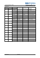
TrustedTM Module T8444 OEM Parameter Description Default Value Notes TICS_CHASSIS The number of the TrustedTM Chassis where the Primary I/O module is installed 1 The TrustedTM Controller Chassis is 1, and Trusted Expander Chassis are 2 to 15 TICS_SLOT The slot number in the chassis where the Primary I/O module is installed 1 The I/O module slots in the TrustedTM Controller chassis are numbered from 1 to 8.
TrustedTM Module T8444 3.2.2.
TrustedTM Module T8444 3.2.3.
TrustedTM Module T8444 3.2.5. Rack 5: Line_Flt Channel Description 1 Field output channel 1 line fault 2 Field output channel 2 line fault 40 Field output channel 40 line fault Table 9 Rack 5: Line_Flt descriptions The line fault input state is reported as true (logic ‘1’) for a line fault condition (open circuit, short circuit, and no field supply voltage). The logic state is the majority voted value. 3.2.6.
TrustedTM Module T8444 3.2.7.
TrustedTM Module T8444 Each input within the housekeeping rack is reported as an integer. In general, the application engineer will not normally require these inputs. They are provided to aid fault finding and diagnosis and may be used for reporting and display purposes. 3.2.8.
TrustedTM Module T8444 4. Operation 4.1. Front Panel Status indicators on the front panel of the module provide visual indications of the module’s operational status and field status. Each indicator is a bicolour LED. Located at the top and bottom of each module is an ejector lever that is used to remove the module from the chassis. Limit switches detect the open/closed position of the ejector levers.
TrustedTM Module T8444 4.2. Module Status LEDs There are six module status indicators on the module front panel: three Healthy, one Active, one Standby, and one Educated. The Healthy indicators are controlled directly by each module slice. The Active, Standby, and Educated indicators are controlled by the FPU. The FPU receives data from each of the module slices. The FPU performs a 2-oo-3 vote on each data bit from the slices and sets the indicators accordingly.
TrustedTM Module T8444 4.3. I/O Status LEDs There are 40 channel status indicators on the module front panel, one for each field input/output. These indicators are controlled by the FPU. The FPU receives data from each of the module slices. The FPU performs a 2-oo-3 vote on each data bit from the slices and sets the indicators accordingly. The input/output status indicator mode is dependent upon the numerical state of the channel.
TrustedTM Module T8444 4.3.2.
TrustedTM Module T8444 4.4. Output and Input separation/Channel allocation The Module has 6 pulse outputs 12 pulse inputs and 2 control signals per motor drive. The output module has 5 power groups protected by Group Fail safe switches. In order to minimise the effect of a single group failure the I/O is segregated as shown below.
TrustedTM Module T8444 5. Fault Finding and Maintenance 5.1. Fault Reporting Module faults are reported to the user through visual indicators on the front panel of the module and through status variables which may be automatically monitored in the application programs and external system communications interfaces. There are generally two types of faults that must be remedied by the user: external wiring and module faults.
TrustedTM Module T8444 5.4. Companion Slot TM For a Companion Slot configuration, two adjacent slots in a Trusted Chassis are configured for the same input module function. One slot is the primary slot and the other a unique secondary (or spare) TM slot. The two slots are joined at the rear of the Trusted Chassis with a double-wide I/O Interface Cable that connects both slots to common field wiring terminations.
TrustedTM Module T8444 5.7. Transfer between Active and Standby Modules The TMR Processor is responsible for managing a pair of I/O modules through an active/standby changeover. The following rules apply to active/standby changeovers, though the TMR Processor and not the I/O module enforce them: • The user must define the primary, and optionally the secondary, I/O module location for each I/O module pair.
TrustedTM Module T8444 6. Technical specification 6.1. Introduction The Pulse Generator and Monitoring module is required to be high integrity but it is not in itself intended to be a safety system. The design concept maintains the advantages of TMR systems while retaining a simple implementation of a Damper Rod control system by the use of redundant paths. The PG/M generates a series of waveforms which rotate a stepper motor in either a clockwise or anti clockwise direction.
TrustedTM Module T8444 6.2. Phase Rotation PHASE 1 _|WWWWW|_______|WWWWW|_______|WW PHASE 2 ___|WWWWW|_______|WWWWW|_______| PHASE 3 _____|WWWWW|_______|WWWWW|______ PHASE 4 _______|WWWWW|_______|WWWWW|____ PHASE 5 WW|_______|WWWWW|_______|WWWWW|__ PHASE 6 WWWW|_______|WWWWW|_______|WWWWW| | FREQ. 1 | T1 T2 | T3 | TIME TIME TIME T1 T2 T3 437.5 MS 312.5 MS 125.0 MS 43.75 MS 31.25 MS 12.5 MS (1.33 HZ) FREQ. 2 (13.3 HZ) NOTE : TIMING IS SHOWN FOR CLOCKWISE ROTATION OF STEPPING MOTOR.
TrustedTM Module T8444 6.3. Fail Safe actions This is not a safety system. Other equipment must be supplied for removing the power from the motor drive circuits in an emergency. Fail safe action in this case is to maintain control of the rods whenever possible even if a fault is detected in the control Module. For example a slice fault will be logged and TM annunciated to the Trusted controller but it will not result in the module entering the “Fatal” state.
TrustedTM Module T8444 6.6. Operation with one thyristor driver removed The Pulse Generator and Monitoring Module interfaces to two Thyristor drivers from each channel. The design is such that each channel can operate with one thyristor driver removed. Loss of feedback from both thyristor drivers of one rod does not affect control of any other rods. 6.7.
TrustedTM Module T8444 6.9. Detection of a short/ long pulse Deviation of pulse length is detected. This is performed by a window detector should a pulse feedback start late or complete early a fault is indicated. The fault detection window is 15mS. Initiating Pulse Feedback Pulse Acceptable window Acceptable Window Input Removed Normal Waveform 8mS Output Off The window for short and long pulse width is 15mS.
TrustedTM Module T8444 6.12. Inference of Position from Motor Pulses Position is inferred by counting the number of pulses generated by the module (not the number of Pulses fed back from the motor drivers). All 6 phases are be used to operate the counter. The counter counts up when the Rod is withdrawn and down when the Rod is inserted. A count of Zero is expected to be with the rod at rest and fully inserted. 6.13.
TrustedTM Module T8444 6.18. Module Temperature Measurement Temperature measurements are made on the module for general monitoring purposes. These are indicative only and are not intended to provide accurate temperature readings. 6.19. Diagnostics TM Wherever possible the Trusted standard diagnostics have been maintained. Because of the nature of the design these have been modified so as not to escalate any failures to a position which would result in a rod motor being de energised.
TrustedTM Module T8444 6.20.
TrustedTM Module T8444 6.21.
TrustedTM Module T8444 7. Specifications System Supply Voltage Circuit Type Number of Channels Independent Power Groups Operational Output/Field Voltage Range Output Voltage Measurement Range Maximum Withstanding Output Current Rating (Continuous) Minimum On State Load Current Output Off State Resistance (effective leakage) Maximum capacitance 20-32Vdc Fault tolerant, fully triplicated with optional line monitoring 40 Channels 5 each of 8 outputs 18 to 60V dc 0 to 60V dc -1 to 60V dc 0.
TrustedTM Module T8444 This page is intentionally blank Issue 09 Apr 10 PD-T8444 45