
User guide

Trusted
TM
Module T8442
Issue 8 Apr 10 PD-T8442 54
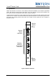
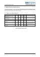
4.2. Rotating Machine Group - Status Indicators
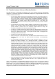
Front panel status indication is provided for each rotating machine group.
Figure 8 shows the indicator arrangement for one rotating machine group.
1
2
3
4
5
Group n
Speed Input Channel 1
Speed Input Channel 2
Speed Input Channel 3
Over-speed
Trip Output
Over-acceleration
Trip Output
Figure 8 Rotating Machine Group Status Indicators
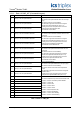
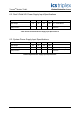
Speed input channels report their status as one of eight pre-defined Input states.
Table 19 shows the default relationship between the input operational state and its associated indicator
state.
Input State Description Indicator State
0 State invalid Off
1 DC low (gear valley) Off
2 DC high (gear tooth) Off
3 Sensor fault (channel discrepancy) Green - flashing
4 Normal operating speed range Green
5 Over-Acceleration trip threshold exceeded Red
6 Over-Speed trip threshold exceeded Red
7 State faulted or unknown Red - flashing
Table 19 Default Speed input Channel Status Indication