
User guide

Trusted
TM
Module T8442
Issue 8 Apr 10 PD-T8442 38
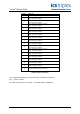
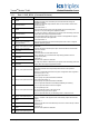
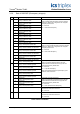
3.2.4. Rack 4 STATE (State Integers)
Ch. Channel Description Detail
1 Group 1, Channel 1, Input State
2 Group 1, Channel 2, Input State
3 Group 1, Channel 3, Input State
4 Group 2, Channel 1, Input State
5 Group 2, Channel 2, Input State
6 Group 2, Channel 3, Input State
7 Group 3, Channel 1, Input State
8 Group 3, Channel 2, Input State
9 Group 3, Channel 3, Input State
Input State:
The digital input state for each of the sensor inputs.
State = 0: State invalid
State = 1: DC low (gear valley)
State = 2: DC high (gear tooth)
State = 3: Sensor fault (channel discrepancy)
State = 4: Normal operating speed range
State = 5: Over-Acceleration trip threshold exceeded
State = 6: Over-Speed trip threshold exceeded
State = 7: Faulted or state unknown
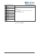
Note:
State 1 and State 2 will only be reported when no new
tooth data is received within 3 seconds. i.e. If at least one
tooth is detected every three seconds then the channel will
be reported as NORMAL State 4.
State 3 will be reported while the input is discrepant unless
the time exceeds the configured Discrepancy Duration
Limit (see 3.1.10) at which point the channel will be
declared as faulted and state 7 will be reported.
10 Group 1, Over-speed coil drive state
11 Group 1, Over-acceleration coil drive state
12 Group 2, Over-speed coil drive state
13 Group 2, Over-acceleration coil drive state
14 Group 3, Over-speed coil drive state
15 Group 3, Over-acceleration coil drive state
Coil Drive State:
The digital output state for each of the coil drive outputs.
Coil Drive State = 0: Invalid
Coil Drive State = 1: No Coil Vfield
Coil Drive State = 2: Coil de-energized
Coil Drive State = 3: Load contacts not connected
Coil Drive State = 4: Coil energized
Coil Drive State = 5: Not used
Coil Drive State = 6: Field Fault. Current is detected when
there should be none, or no current is flowing when there
should be.
Coil Drive State = 7: Faulted or state unknown
Note that there are 4 coils for each output channel. The
reported state reflects the summary state of all the coils
associated with the given channel
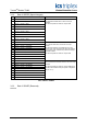
16 Group 1, Over-speed trip state
17 Group 1, Over-acceleration trip state
18 Group 2, Over-speed trip state
19 Group 2, Over-acceleration trip state
20 Group 3, Over-speed trip state
21 Group 3, Over-acceleration trip state
Trip State:
The output trip state for each of the output channels.
Trip State = 2: Channel Tripped
Trip State = 4: Channel Not Tripped
All other states are invalid.
22 Group 1, Over-speed test state
23 Group 2, Over-speed test state
24 Group 3, Over-speed test state
Over-speed test state:
Reports if the group over-speed test is still in effect or has
expired due to a timeout, trip, or reset.
Test State = 0: Not in test mode
Test State = 1: Test mode is active
All other states are invalid.
Table 10 Rack 4: STATE