
User guide

Trusted
TM
Module T8442
Issue 8 Apr 10 PD-T8442 34
R
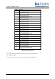
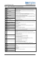
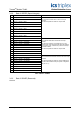
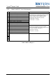
ack I/O Board Description Data Type Direction No. of Channels
1 CMD_BOOL OEM Parameters - - -
C
ommands Boolean In 30
2 SPEED Speed & Acceleration Integer Out 27
3 SPARE Spare Integer Out -
4 STATE I/O Channel Status Integer Out 24
5 LINE_FLT Line Fault Status Boolean In 21
6 DISCREP Channel Discrepancy Integer Out 3
7 HKEEPING Housekeeping Registers Integer Out 57
8 INFO I/O Module Information Integer Out 11
9 FB_INT Threshold feedback Integer Out 12
10 CMD_INT Commands Integer In 21
Table 6 Complex Equipment Definition
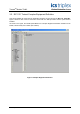
There are two OEM parameters included in the first rack. These OEM parameters define the primary
module position by declaring the module’s chassis and slot location. There is no need to define the
secondary module position within the IEC1131 TOOLSET. Where systems may be required to start-
up with a module in the secondary position as the active module, e.g. the primary module is not
installed when the application is started, then the secondary module’s position should be declared in
the module definition dialog of the System Configuration Manager.
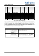
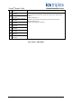
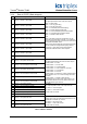
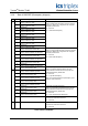
OEM Parameter Description Notes
TICS_CHASSIS The number of the
Trusted
TM
Chassis
where the primary
Speed Monitor is
installed
The Trusted
TM
Controller Chassis is 1, and Trusted
TM
Expander Chassis are 2 to 15.
TICS_SLOT The slot number in the
chassis where the
primary Speed Monitor
is installed
The I/O module slots in the Trusted
TM
Controller
chassis are numbered from 1 to 8. The I/O Module
slots in the Trusted
TM
Expander Chassis are
numbered from 1 to 12.
Table 7 OEM Parameters