
User guide

Trusted
TM
Module T8442
Issue 8 Apr 10 PD-T8442 20
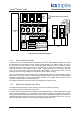
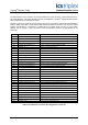
2.3. Field Interface Connector
The field interface on the module is via a 96 way DIN41612 C type connector. These mates with a TC-
801 cable assembly. The cable assembly must be pre-installed in a Trusted
TM
chassis I/O slot that has
been configured for use with T8442 module.
T
he field connector is made up of three columns of 32 pins. The functions of these pins are detailed in
Table 2, Table 3 and Table 4. Note that the table below is provided for reference only, since the T8442
module must always be connected to a T8446 SIFTA for speed inputs, and one or more T8891
SOFTA units for outputs. Direct connection of the field interface connector to field devices is not
supported.
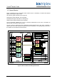
Pin Signal Name Description
A1 SMART_A Smart Slot Link A
A2 - Not used
A3 PASSIVE_PULSE_POS_G1_3 Group 1, Channel 3, Positive Passive Speed input
A4 PASSIVE_PULSE_NEG_G1_3 Group 1, Channel 3, Negative Passive Speed input
A5 PASSIVE_PULSE_MID_G1_3 Group 1, Channel 3, Passive Speed input Bias
A6 SENSOR_G1_1 Group 1, Current Sensor Input 1
A7 SENSOR_G1_3 Group 1, Current Sensor Input 3
A8 COIL_DRIVE_G1_Q1_1 Group 1, Quad 1, Channel 1, Relay coil drive output.
A9 COIL_DRIVE_G1_Q2_1 Group 1, Quad 2, Channel 1, Relay coil drive output.
A10 COIL_DRIVE_G1_Q3_1 Group 1, Quad 3, Channel 1, Relay coil drive output.
A11 COIL_DRIVE_G1_Q4_1 Group 1, Quad 4, Channel 1, Relay coil drive output.
A12 CONTACTS_G1 Group 1, Relay contact status input.
A13 PASSIVE_PULSE_POS_G2_3 Group 2, Channel 3, Positive Passive Speed input
A14 PASSIVE_PULSE_NEG_G2_3 Group 2, Channel 3, Negative Passive Speed input
A15 PASSIVE_PULSE_MID_G2_3 Group 2, Channel 3, Passive Speed input Bias
A16 SENSOR_G2_1 Group 2, Current Sensor Input 1
A17 SENSOR_G2_3 Group 2, Current Sensor Input 3
A18 COIL_DRIVE_G2_Q1_1 Group 2, Quad 1, Channel 1, Relay coil drive output.
A19 COIL_DRIVE_G2_Q2_1 Group 2, Quad 2, Channel 1, Relay coil drive output.
A20 COIL_DRIVE_G2_Q3_1 Group 2, Quad 3, Channel 1, Relay coil drive output.
A21 COIL_DRIVE_G2_Q4_1 Group 2, Quad 4, Channel 1, Relay coil drive output.
A22 CONTACTS_G2 Group 2, Relay contact status input.
A23 PASSIVE_PULSE_POS_G3_3 Group 3, Channel 3, Positive Passive Speed input
A24 PASSIVE_PULSE_NEG_G3_3 Group 3, Channel 3, Negative Passive Speed input
A25 PASSIVE_PULSE_MID_G3_3 Group 3, Channel 3, Passive Speed input Bias
A26 SENSOR_G3_1 Group 3, Current Sensor Input 1
A27 SENSOR_G3_3 Group 3, Current Sensor Input 3
A28 COIL_DRIVE_G3_Q1_1 Group 3, Quad 1, Channel 1, Relay coil drive output.
A29 COIL_DRIVE_G3_Q2_1 Group 3, Quad 2, Channel 1, Relay coil drive output.
A30 COIL_DRIVE_G3_Q3_1 Group 3, Quad 3, Channel 1, Relay coil drive output.
A31 COIL_DRIVE_G3_Q4_1 Group 3, Quad 4, Channel 1, Relay coil drive output.
A32 CONTACTS_G3 Group 3, Relay contact status input.
Table 2 Field Interface Connector Pin Assignment (column A)