
User guide

Trusted
TM
Module T8442
Issue 8 Apr 10 PD-T8442 14
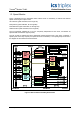
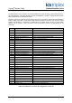
1.3. Speed Monitor
Figure 3 illustrates how the assemblies utilise various levels of redundancy to achieve fault tolerant
speed monitoring and output control.
H
IU Interface (quad-redundant, Q1 through Q4)
Relay Drives (quad-redundant, Q1 through Q4)
Pulse Detectors (triple-redundant, Q1 through Q3)
Status Monitors (dual-redundant, Q1 through Q2)
The four quadrants, labelled Q1 to Q4, are completely independent of each other, and behave as
separate fault containment regions (FCRs).
The I/O circuits are divided into three galvanically isolated speed groups, each group containing 3
speed inputs and 2 relay outputs (over-speed and over-acceleration). The speed groups are shown in
the diagram as three stacked functional blocks.
Figure 3 SFIU and SFTU Assembly Architecture