TrustedTM PD-T8442 TrustedTM TMR Speed Monitor Introduction TM The Trusted T8442 TMR Speed Monitor monitors the shaft speed and acceleration of rotating machinery. It provides machine protection for over-speed and over-acceleration shutdown functions. Typical machinery applications include steam and gas turbines driving pumps, compressors and TM generators.
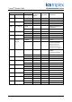
TrustedTM Module T8442 Issue Record Issue Number Date Draft A 1 Sept 04 Draft B 14 Sept 04 Draft C st Revised by Technical Check Authorised by Modification I Jones th I Jones 29 Sept 04 th I. Jones Changes resulting from CDR#4 8442 Draft D 4-Jan 04 R McLin Speed probe defined 1 March 05 J Bourn 2 July 05 J W Clark Format Aug 05 J W Clark Sect 6.5 400w Power requirement deleted G Creech R Cockman Removed Sect 5.
TrustedTM Module T8442 This page is intentionally blank Issue 8 Apr 10 PD-T8442 3
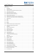
TrustedTM Module T8442 Table of Contents Product Range..........................................................................................................................................9 1. Description .................................................................................................................................10 1.1. Product Overview.......................................................................................................................10 1.2.
TrustedTM Module T8442 3.1.12. Acceleration Filter Default Checkbox.........................................................................................28 3.1.13. Output Non-Latching Checkbox.................................................................................................28 3.1.14. Output Auto-Reset Checkbox ....................................................................................................29 3.1.15. Relay Energise to Trip (ETT) Checkbox .................................
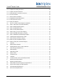
TrustedTM Module T8442 Figures Figure 1 Module Architecture..................................................................................................................10 Figure 2 Functional Block Diagram ........................................................................................................12 Figure 3 SFIU and SFTU Assembly Architecture ...................................................................................14 Figure 4 Module polarisation ..................................
TrustedTM Module T8442 Notice The content of this document is confidential to ICS Triplex Technology Ltd. companies and their partners. It may not be given away, lent, resold, hired out or made available to a third party for any purpose without the written consent of ICS Triplex Technology Ltd. This document contains proprietary information that is protected by copyright. All rights are reserved.
TrustedTM Module T8442 Revision and Updating Policy All new and revised information pertinent to this document shall be issued by ICS Triplex Technology Ltd. and shall be incorporated into this document in accordance with the enclosed instructions. The change is to be recorded on the Amendment Record of this document.
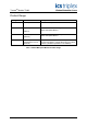
TrustedTM Module T8442 Product Range Catalogue No. Product name Description T8442 TMR Speed Monitor. Trusted T8846 Speed Input FTA Input field termination assembly for use with the T8442 TMR Speed Monitor. (SIFTA) T8891 TC-801 Speed Output FTA TM TMR Speed Monitor Module. (SOFTA) Output field termination assembly for use with the T8442 TMR Speed Monitor.
TrustedTM Module T8442 1. Description 1.1. Product Overview This section gives a brief overview of the input to output architecture of the T8442 Speed Monitor Module showing the methods that are employed to achieve fault tolerant operation.
TrustedTM Module T8442 The quad redundant relay output stage is located on the T8891 SOFTA and is arranged as a fault tolerant structure. The four force guided relay contacts are connected in a series/parallel arrangement to ensure that any single failure cannot affect the desired load state. Diagnostics detect the current in each series leg of the relay structure. The force guided auxiliary contacts are monitored to confirm contact transition.
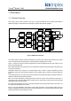
TrustedTM Module T8442 A B C DSP DSP DSP SHIA SHIA SHIA Host Interface Unit (HIU) IMB (TrustedTM System Interface) T8891 SOFTA Cmd Voting and Response Distribution SFIA Q1 Front Panel Unit (FPU) SFIA Q2 SFIA Q3 SFIA Q4 Speed Field Interface Unit (SFIU) T8846 SIFTA Smart Slot Link Isolation Boundary (Power & Sigs) Pulse Detectors (Triple) Relay Drivers (Quad) Monitoring contacts, imon, vmon (Dual) Pulse Inputs T8891 Output SOFTA Relays T8891 Output (Quad) SOFTA Relays Output (Quad) Out
TrustedTM Module T8442 1.2.3. Speed Field Termination Unit (SFTU) The Field Termination Unit (FTU) connects the FIU to the field. The T8442 module FTU is referred to as the SFTU. The SFTU allows speed input signals and shutdown output signals to be routed from the SFIU to the field connector. It also converts the 24 Vdc field power supply into dual redundant ±15 Vdc power for the SOFTA relay current sensors and quad 24 Vdc power for the SFIU relay drivers.
TrustedTM Module T8442 1.3. Speed Monitor Figure 3 illustrates how the assemblies utilise various levels of redundancy to achieve fault tolerant speed monitoring and output control. HIU Interface (quad-redundant, Q1 through Q4) Relay Drives (quad-redundant, Q1 through Q4) Pulse Detectors (triple-redundant, Q1 through Q3) Status Monitors (dual-redundant, Q1 through Q2) The four quadrants, labelled Q1 to Q4, are completely independent of each other, and behave as separate fault containment regions (FCRs).
TrustedTM Module T8442 The quad-redundant relay architecture provides fault tolerant control of the volt-free output and allows a single relay to be tested without disturbing the load. ISENSE and CONTACT data from the SOFTA is analysed to determine if each relay is operable and if a load is connected (de-energise to trip only). ISENSE is an analogue signal that represents the load current in each relay leg (of the quad-voted output).
TrustedTM Module T8442 1.3.3. SIFTA Each T8442 Speed Monitor Module hot swap pair requires a single T8846 SIFTA when installed in a TM Trusted system. The SIFTA has nine identical speed transducer signal conditioning circuits arranged as three groups of three. Each of the three groups is an isolated entity, with its own field power and I/O signal interfaces. A single transducer signal on the SIFTA is taken to three monitoring circuits on the T8442. A fault causes that transducer to fail safe.
TrustedTM Module T8442 1.3.5. Common TrustedTM System I/O Safety Features TM The following list details common safety strategies employed on Trusted which apply to the T8442: series 8000 I/O modules • Module faults are reported through the module front panel LED indicators and via status variables in the IEC1131 Toolset application program. There are two main types of faults: external wiring and module/FTA faults. The module detects wiring faults through dedicated hardware and software.
TrustedTM Module T8442 1.3.6. Speed Monitor Module Safety Features The T8442 system is able to provide uninterrupted functionality, speed monitoring and output control functions under the following circumstances: TM • Complete failure of Trusted • Complete failure of any or all communication links between the T8442 and the Trusted system processors.
TrustedTM Module T8442 2. Installation 2.1. Module Insertion/Removal CAUTION: The module contains static sensitive parts. Static handling precautions must be observed. Specifically ensure that exposed connector pins ARE NOT TOUCHED. Under no circumstances should the module housing BE REMOVED. Before installation, visually inspect the module for damage. Ensure that the module housing appears undamaged and inspect the I/O connector at the back of the module for bent pins.
TrustedTM Module T8442 2.3. Field Interface Connector The field interface on the module is via a 96 way DIN41612 C type connector. These mates with a TCTM 801 cable assembly. The cable assembly must be pre-installed in a Trusted chassis I/O slot that has been configured for use with T8442 module. The field connector is made up of three columns of 32 pins. The functions of these pins are detailed in Table 2, Table 3 and Table 4.
TrustedTM Module T8442 Pin Signal Name Description B1 SMART_B Smart Slot Link B B2 - Not used B3 PASSIVE_PULSE_POS_G1_2 Group 1, Channel 2, Positive Passive Speed input B4 PASSIVE_PULSE_NEG_G1_2 Group 1, Channel 2, Negative Passive Speed input B5 PASSIVE_PULSE_MID_G1_2 Group 1, Channel 2, Passive Speed input Bias B6 SENSOR_G1_2 Group 1, Current Sensor Input 2 B7 SENSOR_G1_4 Group 1, Current Sensor Input 4 B8 COIL_DRIVE_G1_Q1_2 Group 1, Quad 1, Channel 2, Relay coil drive output.
TrustedTM Module T8442 Pin Signal Name Description C1 SMART_C Smart Slot Link C C2 - Not used C3 PASSIVE_PULSE_POS_G1_1 Group 1, Channel 1, Positive Passive Speed input C4 PASSIVE_PULSE_NEG_G1_1 Group 1, Channel 1, Negative Passive Speed input C5 PASSIVE_PULSE_MID_G1_1 Group 1, Channel 1, Passive Speed input Bias C6 VFIELD_P15_G1_1 Group 1, +15V sensor power supply output 1. C7 VFIELD_M15_G1_1 Group 1, -15V sensor power supply output 1.
TrustedTM Module T8442 2.4. TrustedTM Module Polarisation/Keying. All Trusted Modules have been keyed to prevent insertion into the wrong position within a chassis. The polarisation comprises two parts. The module and the associated field cable. Each module type has been keyed during manufacture.
TrustedTM Module T8442 3. Application 3.1. System Configuration This section details speed monitor operating parameters that can be configured through the system configuration tool. Figure 5 shows the Speed monitor configuration template in the system configuration tool. The tool allows configuration of all user adjustable operating parameters required by the speed monitor. The configuration parameters become part of the resulting SYSTEM.INI file which is then transferred to the TM Trusted TMR processors.
TrustedTM Module T8442 3.1.1. Number of Teeth This field can be set for each of the three input channels within a group. The input value configures the number of teeth on the speed sensor gearwheel. It is used to scale the reported rotational speed in RPM. The range of values that can be used for this field are 0 to 1000. The default value is zero. If the number of teeth is set to zero, the channel will be considered disconnected and at zero speed.
TrustedTM Module T8442 3.1.5. Over-Acceleration Limit This field can be set for each input group. The input value configures the over-acceleration threshold ceiling in RPM/second. This defines the maximum over-acceleration threshold level that can be set through the application interface. The overacceleration output will trip when the acceleration is greater than, or equal to, the configured threshold. The range of values that can be used for this field are 0 to 10000. The default value is zero.
TrustedTM Module T8442 Consider the following example: A channel has been configured with an over-acceleration trip threshold of 1000 RPM/second and an over-acceleration deadband value of 950 RPM/second. The channel will trip when the acceleration reaches or exceeds 1000 RPM/second and will not revert to the non-tripped state until the acceleration falls to 50 RPM/second or less. The configuration will appear in the speed monitor configuration template as: OADB 3.1.8.
TrustedTM Module T8442 3.1.10. Discrepancy Duration Limit This field can be set for each input group. The input value configures the time limit in milliseconds, after which discrepant channels within a group are declared faulty. The range of values that can be used for this field are 0 to 65535. The default value is zero. The configured value may be adjusted when the group is at zero speed. A value of 0 will disable both speed and acceleration discrepancy latching (i.e.
TrustedTM Module T8442 3.1.14. Output Auto-Reset Checkbox This checkbox can be set for each output within a group. If an output has been configured as latching (see 3.1.13), setting this checkbox to the ticked state will configure the output for automatic trip reset. For outputs that are configured as non-latching, this configuration item has no effect. Clearing the checkbox (default) will disable the automatic reset function for that output.
TrustedTM Module T8442 3.1.17. SOFTA Present Checkbox This checkbox can be set for each group. If the checkbox is ticked, the Speed Output Field Termination Assembly (SOFTA) is considered to be in use and the front panel indicators will be enabled for normal operation. Clearing the checkbox will disable front panel indicators on the associated group. In this configuration the SOFTA is considered to be unused. The default mode of operation is for the SOFTA to be in use.
TrustedTM Module T8442 3.1.20. Relay Test Selector This selector field can be set globally for the module. The selection in this field configures the behaviour of the automatic relay tests. There are three behaviour types: • Automatic relay testing disabled. • A test time interval may be selected. Relay contact transition tests are performed on each quadrant of the output structure at the interval specified. Background coil testing is enabled in this mode. • Only relay coil testing enabled.
TrustedTM Module T8442 Number Relay Test 0 All automatic relay testing is disabled. 1 Relay quadrant test interval = 37.2 days Relay coil testing is enabled. 2 Relay quadrant test interval = 18.6 days Relay coil testing is enabled. 3 Relay quadrant test interval = 9.30 days Relay coil testing is enabled. 4 Relay quadrant test interval = 4.65 days Relay coil testing is enabled. 5 Relay quadrant test interval = 2.33 days Relay coil testing is enabled. 6 Relay quadrant test interval = 27.
TrustedTM Module T8442 3.2. IEC1131 Toolset Complex Equipment Definition This section details the speed monitor application interface as seen through the IEC1131 TOOLSET. Figure 6 shows a view of the I/O connection screen with one TMR processor and one speed monitor installed.
TrustedTM Module T8442 Rack 1 I/O Board Description Data Type Direction No.
TrustedTM Module T8442 3.2.1. Ch. Rack 1 CMD_BOOL (Command Booleans) Channel Description Detail 1 Group 1 Over-speed command enable Command Enable: 2 Group 1 Over-acceleration command enable 3 Group 2 Over-speed command enable 4 Group 2 Over-acceleration command enable 5 Group 3 Over-speed command enable 6 Group 3 Over-acceleration command enable The outputs will operate under normal under speed monitor control. Configured shutdown states are ignored.
TrustedTM Module T8442 21 Group 3 Over-acceleration trip reset 22 Group 1, Channel 1, Maximum RPM reset. 23 Group 1, Channel 2, Maximum RPM reset. 24 Group 1, Channel 3, Maximum RPM reset. Clears the stored maximum speed value for the associated input channel. 25 Group 2, Channel 1, Maximum RPM reset. Speed monitor operation is unaffected. 26 Group 2, Channel 2, Maximum RPM reset. 27 Group 2, Channel 3, Maximum RPM reset. 28 Group 3, Channel 1, Maximum RPM reset.
TrustedTM Module T8442 3.2.2. Ch. Rack 2 SPEED (Speed Integers) Channel Description Detail 1 Group 1, Channel 1, RPM Revolutions Per Minute: 2 Group 1, Channel 2, RPM 3 Group 1, Channel 3, RPM The instantaneous RPM value for each of the input channels. The values reported are scaled as 1 bit per RPM.
TrustedTM Module T8442 3.2.4. Ch.
TrustedTM Module T8442 3.2.5. Ch. Rack 5 LINE_FLT (Line Fault Integers) Channel Description Detail 1 Group 1, Channel 1, Input line fault Input Line Fault: 2 Group 1, Channel 2, Input line fault 3 Group 1, Channel 3, Input line fault 4 Group 2, Channel 1, Input line fault Asserted TRUE by the System Main Processor if a speed monitor input reports a line fault (State 3) in Rack 4, channels 1 through 9. State 3 is determined by an algorithm that monitors the input dynamically.
TrustedTM Module T8442 3.2.6. Ch.
TrustedTM Module T8442 3.2.7. Ch. Rack 7 HKEEPING (Housekeeping Integers) Channel Description Detail 1 Slice A, 24V2 Input Voltage HIU Housekeeping: 24V1 Input Supply Voltage 2 Slice B, 24V2 Input Voltage The 24V1 Input supply voltage to the speed monitor is reported as an analogue value, scaled in mV.
TrustedTM Module T8442 Ch.
TrustedTM Module T8442 3.2.8.
TrustedTM Module T8442 0x6070 SFIU_STUCK_OFF_FAULT reserved fault code 0x6080 SFIU_STUCK_X_FAULT reserved fault code 0x6090 Qd 0-3 SFIU_LNK_DSCRP_CMD_TST Latent CMD_ERR_A/B/C 0x60A0 Qd 0-3 SFIU_LNK_DSCRP_CFG_TST Latent CFG_ERR_A/B/C 0x60B0 Qd 0-3 SFIU_LNK_DSCRP_CMD_ERR Static CMD_ERR_A/B/C 0x60C0 Qd 0-3 SFIU_LNK_DSCRP_CFG_ERR Static CFG_ERR_A/B/C 0x60Dn Inp SFIU_RPM_DISCREP Slice to Slice RPM discrepancy SFIU_ACCEL_DISCREP Slice to Slice Acceleration discrepancy SFIU_RELAY_CONTAC
TrustedTM Module T8442 0x6Cmn 0x6Cmn Qd Op 0-3 0-5 4+ (Qd Op SFIU_RELAY_DRIVE_XTALK_FAUL T Crosstalk between relay commands, or DIAGs SFIU_RELAY_IMON_XTALK_FAULT Crosstalk between relay IMONs SFIU_IMON_QUAD_DISCREP (LEG1) IMON Leg1 Q1-Q2 Discrepancy SFIU_IMON_QUAD_DISCREP (LEG2) IMON Leg2 Q1-Q2 Discrepancy SFIU_RLY_IMON_LEG_DISCREP IMON Leg to Leg Imbalance SFIU_VMON_QUAD_DISCREP (24V1) 24V1 Q1-Q2 Discrepancy SFIU_VMON_QUAD_DISCREP (24V2) 24V2 Q1-Q2 Discrepancy SFIU_VMON_QUAD_DISCREP (
TrustedTM Module T8442 3.2.9. Ch. Rack 8 INFO (Information Integers) Bit 1 - Description Detail Active module chassis number Active module chassis number: This indicates the chassis location of the currently active Speed Monitor. 2 - Active module slot number Active module slot number: This indicates the slot location within the chassis of the currently active Speed Monitor.
TrustedTM Module T8442 Ch. Bit 1 Description Detail Active Module FCR B Healthy regions (slices) on the active Speed Monitor. Healthy = 0: A slice fault has been detected 2 Active Module FCR C Healthy Healthy = 1: Normal 3 Active Module Ejectors Open Active module ejectors open: This flags the state of the active module ejectors. Ejectors open = 0: Both front panel ejectors are closed. Ejectors open = 1: Both front panel ejectors are open.
TrustedTM Module T8442 3.2.10. Rack 9 FB_INT (Feedback Integers) Ch. Bit Channel Description Detail 1 - Group 1, Over-speed threshold Over-speed threshold: 2 - Group 2, Over-speed threshold This reports the over-speed threshold values in use for each input group. 3 - Group 3, Over-speed threshold The threshold value is reported in RPM.
TrustedTM Module T8442 Ch. Bit Channel Description Detail See 3.1.20 Configured sensor minimum speed value.
TrustedTM Module T8442 Ch. Bit 1 2 3 - 15 Channel Description Detail Group 2, Degrade_3_2_1 (See 3.1.18) Group 3, Degrade_3_2_1 Reserved Reserved for future use.
TrustedTM Module T8442 3.2.11. Rack 10 CMD_INT (Command Integers) Ch. Channel Description Detail Set over-speed threshold: 1 Group 1, Set over-speed threshold 2 Group 2, Set over-speed threshold This sets the over-speed threshold values for each input group. This value comes into force immediately. 3 Group 3, Set over-speed threshold The value will be ignored if it exceeds the configured absolute over-speed threshold limit. (see 3.1.
TrustedTM Module T8442 4. Operation Status LED indicators on the front of the module provide visual feedback of the module’s operational status, field input and output status. Each LED is a tri-colour indicator. During normal operation only two colours are used; red and green which may be steady or flashing. Located at the top and bottom of each module front panel is an ejector lever that is used to remove the module from the chassis.
TrustedTM Module T8442 4.1. Module Status Indicators There are six module status indicators on the module front panel; three Healthy, one Active, one Standby, and one Educated. The Healthy indicators are controlled directly by each module slice. The Active, Standby, and Educated status from each of the three module slices is 2-oo-3 voted by the FPU, and the indicators are set accordingly. The module status indicator states are described in Table 18.
TrustedTM Module T8442 4.2. Rotating Machine Group - Status Indicators Front panel status indication is provided for each rotating machine group. Figure 8 shows the indicator arrangement for one rotating machine group. Speed Input Channel 1 1 Speed Input Channel 2 4 2 Speed Input Channel 3 5 Over-speed Trip Output Over-acceleration Trip Output 3 Group n Figure 8 Rotating Machine Group Status Indicators Speed input channels report their status as one of eight pre-defined Input states.
TrustedTM Module T8442 The Trip output channels also report their status as one of eight pre-defined states. Table 20 shows the default relationship between the Trip output operational state and its associated indicator state.
TrustedTM Module T8442 5. Fault Finding and Maintenance 5.1. Fault Reporting Input module faults are reported to the user through visual indicators (LEDs) on the front panel of the module. Faults are also reported via status variables which may be automatically monitored in the application programs, and external system communications interfaces. There are generally two types of faults that must be remedied by the user; external wiring and module faults.
TrustedTM Module T8442 5.4. Companion Slot TM For a Companion Slot configuration, two adjacent slots in a Trusted Chassis are configured for the same input module function. One slot is the primary slot and the other a unique secondary (or spare) TM slot. The two slots are joined at the rear of the Trusted Chassis with a double-wide I/O Interface Cable that connects both slots to common field wiring terminations.
TrustedTM Module T8442 5.6. Transfer between Active and Standby Modules The TMR Processor is responsible for managing a pair of I/O modules through an active/standby changeover. The following rules apply to active/standby changeovers, though the TMR Processor and not the I/O module enforce them: • The user must define the primary, and optionally the secondary, I/O module location for each I/O module pair.
TrustedTM Module T8442 6. Speed Monitor Specifications The following tables apply to the interface signals existing between the T8442 Speed Monitor module and the SIFTA and SOFTA. Refer to product descriptions PD-T8846 (SIFTA) and PD-T8891 (SOFTA) for the specifications relative to signal field connections. 6.1. Speed Input Specifications Parameter Max.
TrustedTM Module T8442 6.2. Dual VField 24V Power Supply Input Specifications Parameter Min Typ Max Unit Note Input voltage 18 24 32 Vdc w.r.t. VField Return Fused with reverse polarity protection. Input protection Table 22 Dual VField 24V Power Supply Input Specifications 6.3. System Power Supply Input Specifications Parameter Min Typ Max Unit Input voltage 20 24 32 Vdc Power consumption 22 W Note @ 24V dc Input voltage Fused with reverse polarity protection.
TrustedTM Module T8442 6.4. General Module Specifications Parameter Min Typ Max Unit Note Sequence of Events (SOE) Resolution Accuracy 1 -0.5 ms 0.5 ms Field Common Isolation Sustained working 250 Vdc Maximum withstanding 500 VAC Temperature Operating temperature -5 60 °C Storage temperature -25 70 °C 0.5 °C/min 95 %RH Temperature change Humidity Operating humidity 10 Non-Condensing Dimensions Height 266 (10.5) mm (inches) Width 30 (1.