
Owner manual

Trusted
TM
Module T8433
Issue 11 Apr 10 PD-T8433 4
Table of Contents
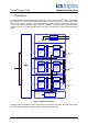
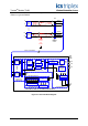
1. Description...................................................................................................................................8
1.1. Isolated Input Field Termination Unit (IIFTU).............................................................................10
1.2. Input Field Interface Unit (IFIU) .................................................................................................10
1.3. Host Interface Unit (HIU) ...........................................................................................................11
1.4. Front Panel Unit (FPU) ..............................................................................................................11
1.5. Line Monitoring Thresholds........................................................................................................12
1.6. Housekeeping............................................................................................................................13
1.7. Fault Detection and Testing .......................................................................................................13
1.8. Sequence of Events Characteristics..........................................................................................13
2. Installation..................................................................................................................................14
2.1. Module Insertion/Removal .........................................................................................................14
2.2. Cable Selection..........................................................................................................................14
2.3. Module Pinout Connections .......................................................................................................15
2.4. Trusted
TM
Module Polarisation/Keying.......................................................................................16
3. Application .................................................................................................................................17
3.1. Module Configuration.................................................................................................................17
3.2. T8433 Complex Equipment Definition .......................................................................................17
3.2.1. Rack 1: THRSHIN......................................................................................................................18
3.2.2. Rack 2: STATE ..........................................................................................................................19
3.2.3. Rack 3: AI ..................................................................................................................................20
3.2.4. Rack 4: THRSHOUT..................................................................................................................21
3.2.5. Rack 5: LINE_FLT .....................................................................................................................21
3.2.6. Rack 6: DISCREP......................................................................................................................22
3.2.7. Rack 7: HKEEPING ...................................................................................................................23
3.2.8. Rack 8: Information....................................................................................................................24
3.3. Sequence of Events Configuration ............................................................................................25
3.4. SYSTEM.INI File Configuration .................................................................................................25
4. Operation ...................................................................................................................................26
4.1. Front Panel ................................................................................................................................26
4.2. Module Status LEDs ..................................................................................................................27
4.3. I/O Status LEDs .........................................................................................................................28
5. Fault Finding and Maintenance..................................................................................................29
5.1. Fault Reporting ..........................................................................................................................29
5.2. Field Wiring Faults .....................................................................................................................29
5.3. Module Faults ............................................................................................................................29
5.4. Companion Slot .........................................................................................................................30
5.5. SmartSlot ...................................................................................................................................30