
Owner manual

Trusted
TM
Module T8433
Issue 11 Apr 10 PD-T8433 19
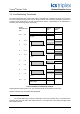
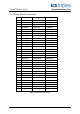
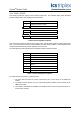
3.2.2. Rack 2: STATE
This board provides the majority voted numerical input state. This indicates within which threshold
band the field input is in and module channel fault status.
Channel Description
1
Field input channel 1 state
2 Field input channel 2 state
20 Field input channel 20 state
21 Field input channel 1 redundant state
40 Field input channel 20 redundant state
Table 6 Rack 2: STATE descriptions
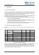
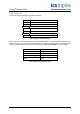
The numerical input state is returned as an integer value; with the least significant 4-bits indicating the
state. The most significant of these 4-bits indicates the channel fault condition; 1 indicating that a fault
has been detected within the internal operation for that channel.
The least significant 3-bits indicate the threshold band within which the input lies.
Value Description
7 Unknown
6 Over-range
5 High-High
4 High
3 Normal
2 Low
1 Low-Low
0 Underrange
Table 7 Rack 2: STATE bit descriptions
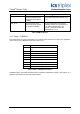
The input channel has a value 7 (Unknown) when:
1. The input channel cannot be correctly measured by two or more slices of the TMR input
module.
2. The TMR Processor detects a 2-oo-3 channel discrepancy between the three slices of the
TMR input module.
3. The module is simulated (not installed or the TMR Processor cannot communicate with 2-oo-
3 slices of the module).