
Manual

Trusted
TM
Module T8432
Issue 16 Apr 10 PD-T8432 17
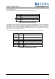
OEM Parameter Description Notes
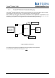
TICS_CHASSIS The number of the
Trusted
TM
Chassis
where the primary I/O
module is installed
The Trusted
TM
Controller Chassis is 1, and
Trusted
TM
Expander Chassis are 2 to 15
TICS_SLOT The slot number in the
chassis where the
primary I/O module is
installed
The I/O module slots in the Trusted
T
M
Controller chassis are numbered from 1 to 8.
The I/O Module slots in the Trusted
TM
Expander Chassis are numbered from 1 to
12
Table 4 OEM Parameters
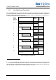
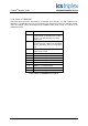
3.2.1. Rack 1: THRSHIN
This board allows the current thresholds for an analogue input channel to be read by the application,
under control of the THRSHOUT board (see section 0).
Channel Description
1 Channel number being read. Range 1 to
60.
2 States 2 > 1 falling threshold
3 States 1 > 2 rising threshold
4 States 3 > 2 falling threshold
5 States 2 > 3 rising threshold
6 States 4 > 3 falling threshold
7 States 3 > 4 rising threshold
8 States 5 > 4 falling threshold
9 States 4 > 5 rising threshold
Table 5 Rack 1: THRSHIN descriptions
THRSHIN reads in the module threshold values controlled by THRSHOUT in Rack 4. See Table 1 for a
graphical representation of the states and thresholds.
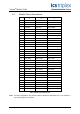
3.2.2. Rack 2: STATE
This board provides the majority voted numerical input state. This indicates within which threshold
band the field input is in and module channel fault status.
Channel Description
1 Field input channel 1 state
2 Field input channel 2 state
60 Field input channel 60 state
Table 6 Rack 2: STATE descriptions
The numerical input state is returned as an integer value; with the least significant 4-bits indicating the
state. The most significant of these 4-bits indicates the channel fault condition; 1 indicating that a fault
has been detected within the internal operation for that channel.