TrustedTM PD-T8431 TrustedTM TMR 24Vdc Analogue Input Module – 40 Channel Introduction TM The Trusted TMR 24V dc Analogue Input module interfaces to 40 sourcing field input devices, acting as a current sink for all these devices. Comprehensive diagnostic tests are performed on each input channel. Fault tolerance is achieved through a Triple Modular Redundant (TMR) architecture within the module for each of the 40 input channels.
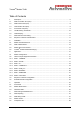
TrustedTM Module T8431 Table of Contents 1. Description ...................................................................................................................................6 1.1. Field Termination Unit (FTU) .......................................................................................................7 1.2. Field Interface Unit (FIU) .............................................................................................................8 1.3. Host Interface Unit (HIU) ..
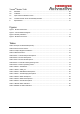
TrustedTM Module T8431 5.5. SmartSlot ...................................................................................................................................28 5.6. Cold Start ...................................................................................................................................28 5.7. Input Channel Calibration Check ...............................................................................................29 5.8.
TrustedTM Module T8431 Notice The content of this document is confidential to ICS Triplex Technology Ltd. companies and their partners. It may not be given away, lent, resold, hired out or made available to a third party for any purpose without the written consent of ICS Triplex Technology Ltd. This document contains proprietary information that is protected by copyright. All rights are reserved.
TrustedTM Module T8431 Revision and Updating Policy All new and revised information pertinent to this document shall be issued by ICS Triplex Technology Ltd. and shall be incorporated into this document in accordance with the enclosed instructions. The change is to be recorded on the Amendment Record of this document.
TrustedTM Module T8431 1. Description TM The TMR 24V dc Analogue Input module is a member of the Trusted range of Input/Output (I/O) TM modules. All Trusted I/O modules share common functionality and form. At the most general level, all I/O modules interface to the Inter-Module Bus (IMB) which provides power and allows TM communication with the Trusted TMR Processor. In addition, all modules have a field interface that is used to connect to module specific signals in the field.
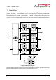
TrustedTM Module T8431 TM Figure 2 shows a simplified functional block diagram of the Trusted 24V dc Analogue Input module. Figure 2 Functional Block Diagram 1.1. Field Termination Unit (FTU) The Field Termination Unit (FTU) is the I/O module assembly that connects all three FIUs to a field connector. The FTU primarily contains passive components necessary for front-end signal TM conditioning.
TrustedTM Module T8431 1.2. Field Interface Unit (FIU) The Field Interface Unit (FIU) is the section of the module that contains the specific circuits necessary to interface to the particular types of field I/O signals. Each module has three FIUs, one per slice. For the TMR 24V dc Analogue Input module, the FIU contains an analogue to digital (A/D) converter for each of the 40 field inputs. The FIU receives isolated power from the HIU for logic.
TrustedTM Module T8431 1.4. Front Panel Unit (FPU) The Front Panel Unit (FPU) comprises a Front Panel Termination Unit (FPTU) and a Front Panel Display Unit (FPDU). The overall FPU contains the necessary connectors, switches, logic, and LED TM indicators for the front panel. For every type of Trusted I/O module, the FPU contains the Slice Healthy, Active/Standby and Educated indicators (LEDs), and the module removal switches.
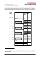
TrustedTM Module T8431 1.5. Line Monitoring Thresholds The module determines the contact state and line fault status by comparing the input voltage level to four user programmed thresholds and two fixed (minimum and maximum) thresholds. Hysteresis is provided on the thresholds by up-scale and downscale values, corresponding to the thresholds for increasing and decreasing values respectively. Typical voltage threshold values Tmax Input Channel State Over-range 6 High-High 5 6.0 T8 2.28 T7 2.24 1.
TrustedTM Module T8431 Default threshold values used for non line monitored inputs are as follows (in raw units) Default = 448, 576, 1344, 1472, 2240, 2368, 3520, 3648, 5120 1.6. Housekeeping The input module automatically performs local measurements of several on-board signals that can be used for detailed troubleshooting and verification of module operating characteristics. Measurements are made within each slice’s HIU and FIU. 1.7.
TrustedTM Module T8431 2. Installation 2.1. Module Insertion/Removal CAUTION: The module contains static sensitive parts. static handling precautions must be observed. Specifically ensure that exposed connector pins ARE NOT TOUCHED. Under no circumstances should the module housing BE REMOVED. Before installation, visually inspect the module for damage. Ensure that the module housing appears undamaged and inspect the I/O connector at the back of the module for bent pins.
TrustedTM Module T8431 2.3.
TrustedTM Module T8431 2.4. TrustedTM Module Polarisation/Keying. TM All Trusted Modules have been Keyed to prevent insertion into the wrong position within a chassis. The polarisation comprises two parts. The module and the associated field cable. Each module type has been keyed during manufacture.
TrustedTM Module T8431 3. Application 3.1. Module Configuration There is no configuration required to the physical input module. All configurable characteristics of the module are performed using tools on the EWS and become part of the application or system.ini file that is loaded into the TMR Processor. The TMR Processor automatically configures the input module after applications are downloaded and during Active/Standby changeover.
TrustedTM Module T8431 OEM Parameter Description Notes TICS_CHASSIS The number of the TrustedTM Chassis where the primary I/O module is installed The TrustedTM Controller Chassis is 1, and TrustedTM Expander Chassis are 2 to 15 TICS_SLOT The slot number in the chassis where the primary I/O module is installed The I/O module slots in the TrustedTM Controller chassis are numbered from 1 to 8. The I/O Module slots in the TrustedTM Expander Chassis are numbered from 1 to 12 Table 4 OEM Parameters 3.2.
TrustedTM Module T8431 3.2.2. Rack 2: STATE This board provides the majority voted numerical input state. This indicates within which threshold band the field input is in and module channel fault status. Channel Description 1 Field input channel 1 state 2 Field input channel 2 state 40 Field input channel 40 state Table 6 Rack 2: STATE descriptions The numerical input state is returned as an integer value.
TrustedTM Module T8431 3.2.3. Rack 3: AI The AI board returns the engineering units for the associated field input. Channel Description 1 Field input channel 1 voltage 2 Field input channel 2 voltage 40 Field input channel 40 voltage Table 8 Rack 3: Channel Field Engineering Units The voltage is the median value taken from the triplicated module. Field input current is converted to voltage using a 250R resistor on a standard field termination assembly (FTA).
TrustedTM Module T8431 3.2.4. Rack 4: THRSHOUT This board allows the current thresholds for an analogue input channel to be read or written by the application. The application can write new thresholds in the THRSHOUT board for a particular channel, and it can read the current thresholds from the THRSHIN board, under control of a channel in the THRSHOUT board. Note that channels 0 and 41 are internal reference channels, and are not connected to the field. Channels 1 to 40 are field channels.
TrustedTM Module T8431 3.2.5. Rack 5: LINE_FLT Channel Description 1 Field input channel 1 line fault 2 Field input channel 2 line fault 40 Field input channel 40 line fault Table 11 Rack 5: LINE_FLT The line fault input state is reported as true (logic ‘1’) for a line fault condition (open circuit, indeterminate, or short circuit condition). The logic state is the majority voted value. 3.2.6.
TrustedTM Module T8431 3.2.7.
TrustedTM Module T8431 Each input within the housekeeping rack is reported as an integer. In general, the application engineer will not normally require these inputs. They are provided to aid fault finding and diagnosis and may be used for reporting and display purposes. If a slice is Fatal, then all reported housekeeping inputs are set to zero. 3.2.8.
TrustedTM Module T8431 The FCR Status channel reports the fault status of the active and standby modules.
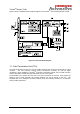
TrustedTM Module T8431 4. Operation 4.1. Front Panel Status LEDs on the front of the module provide visual indications of the module’s operational status and field input status. Each LED is a tri-colour LED of which for normal operation, only two colours are used; red and green. Located at the top and bottom of each module is an ejector lever that is used to remove the module from the chassis. Limit switches detect the open/closed position of the ejector levers.
TrustedTM Module T8431 4.2. Module Status LEDs There are six module status LEDs on the module front panel; three Healthy, one Active, one Standby, and one Educated. The Healthy indicators are controlled directly by each module slice. The Active, Standby, and Educated indicators are controlled by the FPU. The FPU receives data from each of the module slices. The FPU performs a 2-oo-3 vote on each data bit from the slices and sets the indicators accordingly.
TrustedTM Module T8431 4.3. I/O Status LEDs There are 40 input channel status LEDs on the module front panel, one for each field input. These indicators are controlled by the FPU. The FPU receives data from each of the module slices. The FPU performs a 2-oo-3 vote on each data bit from the slices and sets the indicators accordingly. The input status LED mode is dependent upon the voltage level of the field I/O signal.
TrustedTM Module T8431 5. Fault Finding and Maintenance 5.1. Fault Reporting Input module faults are reported to the user through visual indicators (LEDs) on the front panel of the module. Faults are also reported via status variables which may be automatically monitored in the application programs, and external system communications interfaces. There are generally two types of faults that must be remedied by the user; external wiring and module faults.
TrustedTM Module T8431 5.4. Companion Slot TM For a Companion Slot configuration, two adjacent slots in a Trusted Chassis are configured for the same input module function. One slot is the primary slot and the other a unique secondary (or spare) TM slot. The two slots are joined at the rear of the Trusted Chassis with a double-wide I/O Interface Cable that connects both slots to common field wiring terminations.
TrustedTM Module T8431 5.7. Input Channel Calibration Check It is recommended that you carry out a check at 2 yearly intervals on the input channel calibration. This check will detect long term drift and any inaccuracy as a result.
TrustedTM Module T8431 Under normal conditions, an active/standby changeover will only occur if the new active module is fault-free. Under some circumstances, it is desirable to be able to force a changeover to a known faulted module. This can be accomplished by opening the Module Removal switches on the currently active module and pressing the push-button reset on the TMR Processor. This will force the changeover to proceed even if the new active module is not fault free.
TrustedTM Module T8431 6. Specifications System Supply Voltage Range 20 to 32V dc Number of Inputs 40 Channels User Defined Thresholds 4-off Input Current Range 0-22mA Input Voltage Range 0-6 Vdc Sample Update Time 0.5ms Resolution 3.9uA (1/256mA) Safety Accuracy +/- 1% of full scale (default threshold above which 0x70nn series slice discrepancy faults are raised) Calibration Accuracy 0.
TrustedTM Module T8431 This page is intentionally blank Issue 16 Sep 11 PD-T8431 32