TrustedTM PD-T8424 TrustedTM TMR 120VAC Digital Input Module – 40 Channel Introduction TM The Trusted TMR 120VAC Digital Input interfaces to 40 field input devices. Fault tolerance is achieved through a Triple Modular Redundant (TMR) architecture within the module for each of the 40 input channels. Each field input is triplicated and the input voltage is measured using a sigma-delta input circuit.
TrustedTM Module T8424 Table of Contents 1. Description ...................................................................................................................................6 1.1. Field Termination Unit (FTU) .......................................................................................................7 1.2. Field Interface Unit (FIU) .............................................................................................................8 1.3. Host Interface Unit (HIU) ..
TrustedTM Module T8424 5.5. SmartSlot ...................................................................................................................................25 5.6. Cold Start ...................................................................................................................................25 5.7. Transfer between Active and Standby Modules ........................................................................26 6. Specifications .........................................
TrustedTM Module T8424 Notice The content of this document is confidential to ICS Triplex Technology Ltd. companies and their partners. It may not be given away, lent, resold, hired out or made available to a third party for any purpose without the written consent of ICS Triplex Technology Ltd. This document contains proprietary information that is protected by copyright. All rights are reserved.
TrustedTM Module T8424 Revision and Updating Policy All new and revised information pertinent to this document shall be issued by ICS Triplex Technology Ltd. and shall be incorporated into this document in accordance with the enclosed instructions. The change is to be recorded on the Amendment Record of this document.
TrustedTM Module T8424 1. Description TM TM The Trusted TMR 120VAC Digital Input is a member of the Trusted range of Input/Output (I/O) TM modules. All Trusted I/O modules share common functionality and form. At the most general level, all I/O modules interface to the Inter-Module Bus (IMB) which provides power and allows TM communication with the Trusted TMR Processor. In addition, all modules have a field interface that is used to connect to module specific signals in the field.
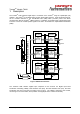
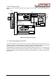
TrustedTM Module T8424 TM Figure 2 shows a simplified functional block diagram of the Trusted Module.
TrustedTM Module T8424 1.2. Field Interface Unit (FIU) The Field Interface Unit (FIU) is the section of the module that contains the specific circuits necessary to interface to the particular types of field I/O signals. Each module has three FIUs, one per slice. For TM the Trusted TMR 120VAC Digital Input, each FIU contains an individual analogue to digital (A/D) converter for each of the 40 field inputs.
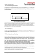
TrustedTM Module T8424 1.5. Line Monitoring Thresholds The T8424 Input module provides thresholds on the AC input amplitude that are in accordance with the requirements of IEC61131-2. (sec 5.2.3) Amplitudes above 82VAC are reported as ON (state 4), and amplitudes below 26VAC are reported as OFF (state 2). The range between these two values provides the hysteresis. States 4 2 26V+/-10% 82V+/-10% Input Voltage (RMS) Figure 3 Input Monitoring Thresholds Line monitoring is not provided by the module.
TrustedTM Module T8424 Each field input is connected to a single bit sigma-delta analogue to digital converter. These circuits, one per channel on each slice, produce a digital output signal which is dynamic in nature. Failures in the circuit components cause the signal to saturate to stuck-on or stuck-off which is automatically detected. Hence, failures are rapidly diagnosed and located.
TrustedTM Module T8424 2. Installation The module must be used together with the AC Digital Input FTA T8824. 2.1. Module Insertion/Removal CAUTION: The module contains static sensitive parts. Static handling precautions must be observed. Specifically ensure that exposed connector pins ARE NOT TOUCHED. Under no circumstances should the module housing BE REMOVED. Before installation, visually inspect the module for damage.
TrustedTM Module T8424 2.3.
TrustedTM Module T8424 2.4. TrustedTM Module Polarisation/Keying. TM All Trusted Modules have been keyed to prevent insertion into the wrong position within a chassis. The polarisation comprises two parts. The module and the associated field cable. Each module type has been keyed during manufacture.
TrustedTM Module T8424 3. Application 3.1. Module Configuration There is no configuration required to the physical input module, (i.e. jumpers, etc.). All configurable characteristics of the module are performed using tools on the EWS and become part of the application or system.ini file that is loaded into the TMR Processor. The TMR Processor automatically configures the input module after applications are downloaded and during Active/Standby changeover.
TrustedTM Module T8424 OEM Parameter Description Notes TICS_CHASSIS The number of the Chassis where the primary I/O module is installed The Controller Chassis is 1, and Expander Chassis are 2 to 15 TICS_SLOT The slot number in the chassis where the primary I/O module is installed The I/O module slots in the Controller chassis are numbered from 1 to 8. The I/O Module slots in the Expander Chassis are numbered from 1 to 12 Table 3 OEM Parameters 3.2.1.
TrustedTM Module T8424 Value Description 7 Faulted 6 N/A 5 N/A 4 Closed contact (ON) 3 N/A 2 Open contact (OFF) 1 N/A 0 FTA to module Open circuit. Table 6 Rack 2: STATE Input Bit descriptions The input channel has a value 7 (Unknown) when: 1. The input channel cannot be correctly measured by two or more slices of the TMR input module. 2. The TMR Processor detects a 2-oo-3 channel discrepancy between the three slices of the TMR input module. 3.
TrustedTM Module T8424 3.2.5. Rack 5: LINE_FLT Channel Description 1 Field input channel 1 line fault 2 Field input channel 2 line fault 40 Field input channel 40 line fault Table 8 Rack 5: Line Fault descriptions The line fault input is reported as true (logic ‘1’) for a line fault condition (for this module, only FTA to module Open Circuit). The logic state is the majority voted value.
TrustedTM Module T8424 3.2.7.
TrustedTM Module T8424 Each input within the housekeeping rack is reported as an integer. In general, the application engineer will not normally require these inputs. They are provided to aid fault finding and diagnosis and are often used for reporting and display purposes. If a slice is off-line, then all reported housekeeping inputs are set to zero. 3.2.8.
TrustedTM Module T8424 Bit 7 6 5 4 3 Standby Module Ejector open FCR C Healthy 2 1 0 FCR B Healthy FCR A Healthy Active Module FCR B Healthy FCR A Healthy Ejectors open FCR C Healthy Table 13 Rack 8: FCR bit descriptions The ‘Primary Module is active’ channel is set to non-zero if the primary module is the current active module, i.e. the active module is in the chassis and slot numbers defined within the OEM parameters.
TrustedTM Module T8424 4. Operation 4.1. Front Panel Status LEDs on the front of the module provide visual indications of the module’s operational status and field input status. Each LED is a tri-colour LED of which for normal operation, only two colours are used; red and green. Located at the top and bottom of each module is an ejector lever that is used to remove the module from the chassis. Limit switches detect the open/closed position of the ejector levers.
TrustedTM Module T8424 4.2. Module Status LEDs There are six module status LEDs on the module front panel; three Healthy, one Active, one Standby, and one Educated. The Healthy indicators are controlled directly by each module slice. The Active, Standby, and Educated indicators are controlled by the TMR processor via the FPU. The FPU receives data from each of the module slices. The FPU performs a 2-oo-3 vote on each data bit from the slices and sets the indicators accordingly.
TrustedTM Module T8424 4.3. I/O Status LEDs There are 40 input channel status LEDs on the module front panel, one for each field input. These indicators are controlled by the FPU. The FPU receives data from each of the module slices. The FPU performs a 2-oo-3 vote on each data bit from the slices and sets the indicators accordingly. Indicator state Description Off Open field switch, OFF state. Green Closed field switch, ON state. Red – flashing Open FTA Cable.
TrustedTM Module T8424 5. Fault Finding and Maintenance 5.1. Fault Reporting Input module faults are reported to the user through visual indicators (LEDs) on the front panel of the module. Faults are also reported via status variables which may be automatically monitored in the application programs, and external system communications interfaces. There are generally two types of faults that must be remedied by the user; external wiring and module faults.
TrustedTM Module T8424 5.5. SmartSlot For a SmartSlot configuration, the secondary slot is not unique to each primary slot. Instead, a single secondary slot is shared among many primary slots. This technique provides the highest density of TM modules to be fitted in a given physical space. At the rear of the Trusted Chassis, a single-wide I/O Cable connects the secondary slot directly to the I/O Cable connected to the failed primary module.
TrustedTM Module T8424 5.7. Transfer between Active and Standby Modules The TMR Processor is responsible for managing a pair of I/O modules through an active/standby changeover. The following rules apply to active/standby changeovers, though the TMR Processor and not the I/O module enforce them: • The user must define the primary, and optionally the secondary, I/O module location for each I/O module pair.
TrustedTM Module T8424 6. Specifications System Supply Voltage Range 20 to 32 Vdc Number of Inputs 40 Channels Input Voltage Range 0VAC - 150VAC Loop current at 120V AC 1.75mA (5.37mA from T8824 rev E) Maximum Sustained Input Voltage 250V (AC RMS or DC) Input Frequency Range 47 – 63 Hz Reported Amplitude Accuracy for Sine Wave Input +/- 10% Turn-on Voltage ~82VAC +/- 18% Turn-off Voltage ~26VAC +/- 18% Circuit Type Fault tolerant, fully triplicated.
TrustedTM Module T8424 This page is intentionally blank Issue 8 Sep 11 PD-T8424 28