Manual
Manuals
Brands
Rockwell Automation Manuals
Equipment
T8311 Trusted Expander Interface
1
2
3
4
5
6
7
8
9
10
Table Of Contents
1. Description
1.1. Overview
1.2. Power Distribution
2. Installation
2.1. Module Installation
2.2. Module Insertion and Removal
2.2.1. Module Replacement
2.3. Expander Bus Connection
2.3.1. Cable Assembly Replacement
2.4. TrustedTM Module Polarisation/Keying
3. Application
3.1. Message Forwarding
3.2. Control Signal Forwarding
3.3. I/O Complex Equipment Definition T8311
3.3.1. Voltage Level Format
3.4. Module Information
3.5. System Initialisation File
3.6. Expander Chassis IMB Connector (SK1)
3.7. Expander chassis Bus Connector (PL4)
4. Operation
4.1. Operating Modes
4.1.1. Standby
4.1.2. Active
4.1.3. Expander Interface Module Active/standby Control
4.2. Communication Busses
4.2.1. Expander bus
4.2.2. Inter-Module Bus
4.3. Front Panel
4.3.1. Healthy Indicator`
4.3.2. Active Indicator
4.3.3. Standby Indicator
5. Fault Finding and Maintenance
5.1. PCBS and Connectors
5.2. Troubleshooting
6. Specifications
Trus
ted
TM
Module T8311
Issue 12 Mar 07
PD-T8311
8
1
.
D
e
s
c
r
i
p
t
i
o
n
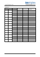
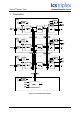
Figure 1 Funct
ional Block Diagram
1
...
...
6
7
8
9
10
...
...
28