TrustedTM PD-T8311 TrustedTM TMR Expander Interface Introduction TM TM The Trusted TMR Expander Interface module resides in the Trusted Controller Chassis and provides the ‘master’ interface between the Inter-Module Bus (IMB) in the Controller Chassis and the Expander Bus. The Expander Bus allows multiple chassis systems to be implemented using UTP cable connections whilst maintaining the fault tolerant, high bandwidth IMB capabilities.
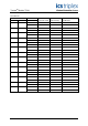
TrustedTM Module T8311 Issue Record Issue Number Date Revised by 9 Oct 05 J W Clark 10 Nov 06 N Owens I Vince P Stock Specification 11 Dec 06 N Owens I Vince P Stock Cable distance 12 Mar 07 N Owens I Vince P Stock System INI Issue 12 Mar 07 Technical Check Authorised by Modification Format PD-T8311 2
TrustedTM Module T8311 This page is intentionally blank Issue 12 Mar 07 PD-T8311 3
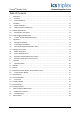
TrustedTM Module T8311 Table of Contents 1. Description......................................................................................................................................8 1.1. Overview ......................................................................................................................................9 1.2. Power Distribution........................................................................................................................9 2. Installation ..
TrustedTM Module T8311 Figures Figure 1 Functional Block Diagram ..........................................................................................................8 Figure 2 Module Polarisation ..................................................................................................................13 Figure 3 Module Front Panel ..................................................................................................................22 Tables Table 1 Chassis Connector (SK1) Pinout.
TrustedTM Module T8311 Notice The content of this document is confidential to ICS Triplex Technology Ltd. companies and their partners. It may not be given away, lent, resold, hired out or made available to a third party for any purpose without the written consent of ICS Triplex Technology Ltd. This document contains proprietary information that is protected by copyright. All rights are reserved.
TrustedTM Module T8311 Revision and Updating Policy All new and revised information pertinent to this document shall be issued by ICS Triplex Technology Ltd. and shall be incorporated into this document in accordance with the enclosed instructions. The change is to be recorded on the Amendment Record of this document.
TrustedTM Module T8311 1.
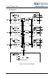
TrustedTM Module T8311 1.1. Overview The TMR Expander Interface is a fault tolerant design based on TMR architecture arranged in a lockstep configuration. Figure 1 shows, in simplified terms, the basic structure of the TMR Expander Interface. The module has three main fault containment regions (FCR A, B and C).
TrustedTM Module T8311 2. Installation 2.1. Module Installation The Expander Interface Modules may reside in any of the I/O slots within the Controller Chassis. The modules are installed in pairs with the left-hand module occupying an odd numbered slot. The Expander Interface must NOT be installed in these other module locations, as this may cause damage to the module. The two Interface slots must be interconnected using the Expander Interface Adaptor Unit T8312.
TrustedTM Module T8311 2.2.1. Module Replacement The replacement module must be inserted in to the vacant processor slot, ensuring that the module is correctly located and the ejector tabs are closed (see 2.2). The newly installed module will perform its power-up sequence.
TrustedTM Module T8311 2.3. Expander Bus Connection Further details of the Expander Bus cable assembly are provided in the associated Product Description (PD-TC300). 2.3.1. Cable Assembly Replacement It is not intended that the cable should need replacement, however this may be achieved by replacement of the complete cable assembly that requires that the system be shutdown. To remove a cable: 1. Ensure that the correct chassis and slot positions are selected. 2.
TrustedTM Module T8311 2.4. TrustedTM Module Polarisation/Keying TM All Trusted Modules have been Keyed to prevent insertion into the wrong position within a chassis. The polarisation comprises two parts. The module and the associated field cable. Each module type has been keyed during manufacture.
TrustedTM Module T8311 3. Application 3.1. Message Forwarding The primary function of the Expander is to provide a method of extending the IMB beyond a single processor chassis. The active TMR Expander Interface Module receives messages from the processor chassis IMB/backplane and forwards them to the Expander Bus when its slot position is enabled. Similarly, the active TMR Expander Processor Module forwards all messages received from the Expander Bus to the addressed Expander Chassis IMB.
TrustedTM Module T8311 3.3. I/O Complex Equipment Definition T8311 The Expander Interface requires no configuration to the module itself. TM Each module fitted in a Trusted system requires an entry in the I/O Connection table, specifying its chassis and slot number. The I/O Complex Equipment Definition allows control of the module’s functions, and provides information on its status. For information on editing the I/O Connection table, refer to PD-8082B. The definition for this module is described below.
TrustedTM Module T8311 APPENDIX: Note: Bit 0 AM slice A: 1 - Slice is responding and there are no slice errors. 0 - Slice is either NOT responding or there is a slice error. Bit 1 AM slice B: 1 - Slice is responding and there are no slice errors. 0 - Slice is either NOT responding or there is a slice error. Bit 2 AM slice C: 1 - Slice is responding and there are no slice errors. 0 - Slice is either NOT responding or there is a slice error. Bit 3 AM ejectors open: 1 - AM ejectors open.
TrustedTM Module T8311 3.4. Module Information The following information is recorded by the TMR Expander Interface Module and made available to the TMR Processor. • Expander Bus link quality, including receive error counts for each communications link and link status. • Received message error, on a per link/FCR basis, including frame error, checksum error and discrepancy. • HIFT Clock, master and slave clock status, and master/slave switching. • FCR watchdog status. • Current active/standby status.
TrustedTM Module T8311 3.6. Expander Chassis IMB Connector (SK1) SK1 is a 185-way DIN41642 type connector.
TrustedTM Module T8311 3.7. Expander chassis Bus Connector (PL4) PL4 is a 96-way DIN41612, C-type connector.
TrustedTM Module T8311 4. Operation 4.1. Operating Modes 4.1.1. Standby Standby is the default mode of operation for the module, once internal supply levels are established. In this mode the module may respond to command messages addressed to the module itself over the IMB. Communication between the Controller Chassis IMB and the Expansion Chassis is inhibited. 4.1.2.
TrustedTM Module T8311 4.2. Communication Busses 4.2.1. Expander bus Each TMR Expander Interface Module contains a Bus Interface, isolation components and transceivers to the Expander Bus. The triplicated Expander Bus provides communication interconnection between the TMR Processor Chassis and the Expander Chassis at a data transfer rate of 1.5GMbps via UTP cables. 4.2.2. Inter-Module Bus Each TMR Expander Interface Module FCR contains a Bus Interface to the Inter-Module Bus.
TrustedTM Module T8311 4.3.
TrustedTM Module T8311 4.3.1. Healthy Indicator` Three LEDs, one for each of the three channels, indicating the overall health of each processor channel: LED 1 LED 2 LED 3 = = = Channel A Channel B Channel C. A steady green LED indicates a healthy module; a flashing red indicates a fault in the corresponding channel. 4.3.2. Active Indicator This LED is green when the module is in the ‘Active’ mode. 4.3.3. Standby Indicator A steady green LED when the module is in the ‘Standby’ mode.
TrustedTM Module T8311 5. Fault Finding and Maintenance 5.1. PCBS and Connectors The TMR Expander Interface Module comprises a single PCB assembly fitted with two connectors, one each for the Expander Chassis IMB (SK1) and Expander Bus (PL4). These are detailed below. 5.2. Troubleshooting Symptom Possible Cause Solution All front panel indicators off Lack of power If all other modules within the chassis also show no indicators, check the power distribution and connection to the chassis.
TrustedTM Module T8311 Symptom Possible Cause Solution Both active or standby LEDs OFF LED failure This condition may be indicated briefly during module power-up. All other modules within the chassis indicate standby mode. TMR Processor not running (faulted, or application not started). Verify the condition of the TMR processor and start the application as necessary.
TrustedTM Module T8311 6.
TrustedTM Module T8311 This page is intentionally blank Issue 12 Mar 07 PD-T8311 27