TrustedTM Module T8310 TrustedTM TMR Expander Processor Introduction TM TM The Trusted TMR Expander Processor module resides in the processor slots of the Trusted Expander Chassis and provides the ‘slave’ interface between the Expansion Bus and the Expander Chassis backplane. The Expander Bus allows multiple chassis systems to be implemented using UTP cable connections whilst maintaining the fault tolerant, high bandwidth IMB capabilities.
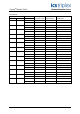
TrustedTM Module T8310 Issue Record Issue Number Date 9 Oct 05 10 Aug 06 N Owens I Vince P Stock Corrections 11 Nov 06 N Owens I Vince P Stock Specifications 12 Dec 06 N Owens I Vince P Stock Cable Distance Issue 12 Dec 06 Revised by Technical Check Authorised by Modification Format PD-T8310 2
TrustedTM Module T8310 This page is intentionally blank Issue 12 Dec 06 PD-T8310 3
TrustedTM Module T8310 Table of Contents 1. Description ...................................................................................................................................8 1.1. Overview ......................................................................................................................................9 1.2. Power Distribution........................................................................................................................9 2. Installation.....
TrustedTM Module T8310 Figures Figure 1 Simplified Block Diagram ...........................................................................................................8 Figure 2 Expander Processor Slots ........................................................................................................10 Figure 3 Expander Processor Cable ......................................................................................................10 Figure 4 Module Polarisation ............................
TrustedTM Module T8310 Notice The content of this document is confidential to ICS Triplex Technology Ltd. companies and their partners. It may not be given away, lent, resold, hired out or made available to a third party for any purpose without the written consent of ICS Triplex Technology Ltd. This document contains proprietary information that is protected by copyright. All rights are reserved.
TrustedTM Module T8310 Revision and Updating Policy All new and revised information pertinent to this document shall be issued by ICS Triplex Technology Ltd. and shall be incorporated into this document in accordance with the enclosed instructions. The change is to be recorded on the Amendment Record of this document.
TrustedTM Module T8310 1.
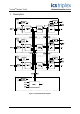
TrustedTM Module T8310 1.1. Overview The TMR Expander Processor is a fault tolerant design based on TMR architecture arranged in a lockstep configuration. Figure 1 shows, in simplified terms, the basic structure of the TMR Expander Processor. The module has three main fault containment regions (FCR A, B and C).
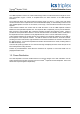
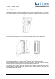
TrustedTM Module T8310 2. Installation The Expander Processor module always resides in one of the two processor (left most - PL1 and PL2) slots within the Expander Chassis. The Expander Processor must NOT be installed in these other module locations, as this may cause damage to the module. Figure 2 Expander Processor Slots The two processor slots must be interconnected using the Cable Hood Assembly shown below.
TrustedTM Module T8310 2.1. Module Insertion and Removal CAUTION: The module contains static sensitive parts. static handling precautions must be observed. Specifically ensure that exposed connector pins ARE NOT TOUCHED. Under no circumstances should the module housing BE REMOVED. Before installation, visually inspect the module for damage. Ensure that the module housing appears undamaged and inspect the I/O connector at the back of the module for bent pins.
TrustedTM Module T8310 In Hot-standby configurations, with both Expander Processor Modules installed, the faulted module may be either the active or the standby module. In most cases the system will automatically switch to the healthiest module, therefore only the standby module will require replacement. To replace the active module follow the steps described above. To replace the standby module: 1. Release both the top and bottom ejectors tabs on the standby module using the ejector release tool. 2.
TrustedTM Module T8310 2.4. Expander Chassis IMB Connector (SK1) SK1 is a 185-way DIN41642 type connector.
TrustedTM Module T8310 2.5. Expander Chassis Bus Connector (PL4) PL4 is a 96-way DIN41612, C-type connector.
TrustedTM Module T8310 2.6. TrustedTM Module Polarisation/Keying TM All Trusted Modules have been Keyed to prevent insertion into the wrong position within a chassis. The polarisation comprises two parts. The module and the associated field cable. Each module type has been keyed during manufacture.
TrustedTM Module T8310 3. Application 3.1. Message Forwarding The primary function of the Expander is to provide a method of extending the IMB beyond a single processor chassis. The active TMR Expander Interface Module receives messages from the processor chassis IMB/backplane and forwards them to the Expander Bus when its slot position is enabled. Similarly, the active TMR Expander Processor Module forwards all messages received from the Expander Bus to the Expander Chassis IMB.
TrustedTM Module T8310 3.4. IMB Power Generation The TMR Expander Processor Modules (both active and standby) generate three independent IMB power supplies. These supplies are provided via a diode to the IMB/backplane. These supplies are used to power the triplicated IMB interfaces within the interface modules within the Expander Chassis. These supplies have a common return, commoned with the module’s internal 0V. Failure of any of these supplies will not affect the remaining supplies.
TrustedTM Module T8310 3.8. Communication Busses 3.8.1. Expander Bus Each TMR Expander Processor Module contains a Bus Interface, isolation components and transceivers to the Expander Bus. The triplicated Expander Bus provides communication interconnection between the TMR Processor Chassis and the Expander Chassis at a data transfer rate of 1.5Gbps via UTP cables. 3.8.2. Inter-Module Bus Each TMR Expander Processor Module FCR contains a Bus Interface to the Inter-Module Bus.
TrustedTM Module T8310 3.10. I/O Complex Equipment Definition T8310 TM Each module fitted in a Trusted system requires an entry in the I/O Connection table, specifying its chassis and slot number. The I/O Complex Equipment Definition allows control of the module’s functions, and provides information on its status. For information on editing the I/O Connection table, refer to PD-8082B. The definition for this module is described below.
TrustedTM Module T8310 APPENDIX: Note: Bit 0 AM slice A: 1 - Slice is responding and there are no slice errors. 0 - Slice is either NOT responding or there is a slice error. Bit 1 AM slice B: 1 - Slice is responding and there are no slice errors. 0 - Slice is either NOT responding or there is a slice error. Bit 2 AM slice C: 1 - Slice is responding and there are no slice errors. 0 - Slice is either NOT responding or there is a slice error. Bit 3 AM ejectors open: 1 - AM ejectors open.
TrustedTM Module T8310 4. Operation 4.1. Standby Standby is the default mode of operation for the module, once internal supply levels are established. In this mode the module may receive messages addressed to the module itself over the IMB or Expander Bus. Response messages over the Expander Bus will only be transmitted following a transition to the Active mode. The module does not provide the capability of passing messages to and from other modules within the Expander Chassis in this mode. 4.2.
TrustedTM Module T8310 4.4.
TrustedTM Module T8310 4.5. Module Status LEDs LED State Description Healthy On Steady Green The Module is healthy. Flashing Red Fault on the corresponding Chanel Active Green Module is in the Active state. Standby On Steady Green Module is in the Standby state. Communications Activity Off No activity or failed Green Receive activity`. Red Transmit activity.
TrustedTM Module T8310 5. Fault Finding and Maintenance 5.1. Fault Reporting Input module faults are reported to the user through visual indicators (LEDs) on the front panel of the module. Faults are also reported via status variables which may be automatically monitored in the application programs, and external system communications interfaces. There are generally two types of faults that must be remedied by the user; external wiring and module faults.
TrustedTM Module T8310 5.3. Troubleshooting Symptom Possible Cause Solution All front panel indicators off Lack of power If all other modules within the chassis also show no indicators, check the power distribution and connection to the chassis. Front panel interface (FCR D) failure Check if other modules within the chassis have LEDs illuminated. Check if it is possible to communicate with other modules within the chassis – using either the chassis board type (T8300) or the diagnostic utility.
TrustedTM Module T8310 Symptom Possible Cause Solution Single activity LED off Expander Interface Module fault Verify that there is a fault within the Expander Interface Module (within the controller chassis). Replace the faulted module as soon as possible. Expander Bus Fault Check the Expander Bus cable assembly is correctly installed at both the expansion and controller chassis. Check that there are no faults within the expander bus cabling, replace any cables found to be defective.
TrustedTM Module T8310 6.