
User guide


Trusted
TM
Expander Chassis T8300
Issue 13 Jul 12 PD-T8300 4
Table of Contents
1. Description...................................................................................................................................... 7
1.1. Inter-Module Bus Backplane ........................................................................................................ 8
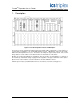
1.2. System Configuration ................................................................................................................... 9
1.3. Bus Terminations ....................................................................................................................... 10
1.4. Bus Connections ........................................................................................................................ 10
1.5. Slot positions .............................................................................................................................. 10
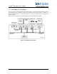
1.6. External Power ........................................................................................................................... 11
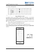
1.7. Smart Slot Referencing .............................................................................................................. 12
1.7.1. Location of Smart slots ................................................................................................................. 12
1.8. I/O Connectors ........................................................................................................................... 13
1.9. Chassis Dimensions .................................................................................................................. 13
2. Installation .................................................................................................................................... 14
3. Specifications ............................................................................................................................... 15
Figures
Figure 1 Trusted
TM
Expander Chassis and Backplane ............................................................................. 7
Figure 2 Inter-Module Bus Backplane ...................................................................................................... 8
Figure 3 Backplane Front View ................................................................................................................. 9
Figure 4 Backplane Back View ............................................................................................................... 11
Figure 5 Chassis 24V dc Input Power Connectors ................................................................................. 11
Figure 6 Molex sockets on the rear of each processor and expander chassis ...................................... 12
Figure 7 Connector to Chassis Attachment Features............................................................................. 13
Figure 8 Chassis Dimensions ................................................................................................................. 13
Figure 9 Installation of Chassis............................................................................................................... 14
Tables
Table 1 System ID Settings ...................................................................................................................... 9