TrustedTM PD-T8300 Trusted TM Expander Chassis Introduction TM The Trusted Expander Chassis can be either swing frame or fixed frame mounted and houses the TM TM Trusted Expander Processors and Trusted I/O Modules. The Chassis may be panel (rear) mounted by the addition of a Panel Mounting Kit T8380 which comprises a pair of brackets with rear facing ears. TM The Inter-Module Bus backplane is part of the Trusted interconnection and other services for the modules.
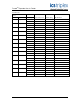
TrustedTM Expander Chassis T8300 Issue Record Issue Number Date Revised by 9 Sep 05 J W Clark 10 Aug 06 N Owens I Vince P Stock TC-006 connection 11 Dec 06 N Owens I Vince P Stock Cable distance 12 Jan 07 N Owens I Vince P Stock Earthing 13 Jul 12 N Owens Issue 13 Jul 12 Technical Check Authorised by Modification Format Correction PD-T8300 2
TrustedTM Expander Chassis T8300 This page is intentionally blank Issue 13 Jul 12 PD-T8300 3
TrustedTM Expander Chassis T8300 Table of Contents 1. Description......................................................................................................................................7 1.1. Inter-Module Bus Backplane ........................................................................................................8 1.2. System Configuration...................................................................................................................9 1.3. Bus Terminations .
TrustedTM Expander Chassis T8300 Notice The content of this document is confidential to ICS Triplex Technology Ltd. companies and their partners. It may not be given away, lent, resold, hired out or made available to a third party for any purpose without the written consent of ICS Triplex Technology Ltd. This document contains proprietary information that is protected by copyright. All rights are reserved.
TrustedTM Expander Chassis T8300 Revision and Updating Policy All new and revised information pertinent to this document shall be issued by ICS Triplex Technology Ltd. and shall be incorporated into this document in accordance with the enclosed instructions. The change is to be recorded on the Amendment Record of this document.
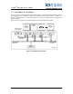
TrustedTM Expander Chassis T8300 1. Description Figure 1 TrustedTM Expander Chassis and Backplane The Chassis may be populated in different ways dependent on the requirements of each System, to accommodate a maximum of 12 single-width (30mm) TrustedTM I/O Modules and up to two singlewidth TrustedTM Expander Processors. The Chassis assembly has eight screw positions, four on each flange, that are used to enable secure attachment to the side brackets on the frame.
TrustedTM Expander Chassis T8300 1.1. Inter-Module Bus Backplane The Chassis houses the Inter-Module Bus backplane which is a single, printed circuit board assembly. The Inter-Module Bus backplane provides the electrical interconnections between modules in a TM Trusted Expander Chassis. These interconnections are part of the physical layer communications between modules. Figure 2 shows a simplified top-level block diagram of the Inter-Module Bus backplane.
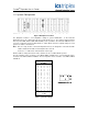
TrustedTM Expander Chassis T8300 1.2. System Configuration Figure 3 Backplane Front View The backplane contains a user-configurable setting for system identification. In the TrustedTM Expander Chassis, this setting represents the system number 0 to 15. The setting is implemented via TM three 4-position DIP switches (IDA, IDB and IDC) and is provided to the Trusted TMR Processor connector. Adjacent to the three DIP switches is a table which shows the required settings for each system.
TrustedTM Expander Chassis T8300 1.3. Bus Terminations The backplane contains termination circuits for certain bus signals. The terminators are used to reduce signal reflections on critical signals and also to provide default logic levels for open or tri-stated signals. Termination circuits are located at the end slot positions, 1 and 14. 1.4. Bus Connections All bus connections are triplicated except for the +24V dc external power supply, which is dual redundant. 1.5.
TrustedTM Expander Chassis T8300 1.6. External Power The backplane has two terminal blocks, one for each of the redundant external +24Vdc power supplies, which are connected to the input power connectors. Redundant power is supplied to all modules in the chassis.
TrustedTM Expander Chassis T8300 1.7. Smart Slot Referencing For a Smart Slot configuration, the secondary slot is not required to be unique to each primary slot. Instead, a single secondary slot can be shared among many primary slots. This technique provides the highest density of modules to be fitted in a given physical space.
TrustedTM Expander Chassis T8300 1.8. I/O Connectors Up to 14 DIN 41612 port connectors, slotted into the chassis back-plate, can be provided for TM TM connecting the Trusted Expander Processors to the Controller and Trusted I/O to the field termination area. Double and single connector options are available.
TrustedTM Expander Chassis T8300 2. Installation The TrustedTM Expander Chassis is installed into a swingframe-mounted, or fixed frame as shown in Figure 9 using M5 x 12 Pan Head Taptites screws. Figure 9 Installation of Chassis Note that only the inner pair of holes in the mounting ears are used at this stage to secure the Chassis in the swingframe.
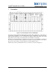
TrustedTM Expander Chassis T8300 3. Specifications Voltage Range 20 to 32V dc Fusing External, 20A Connectors 14 x DIN 41642, male Expander Comms Max Distance Using TC-301 copper cable 30m Using fibre converters 10km Operating Temperature -5°C to 60°C (23°F to 140°F) Non-operating Temperature -25°C to 70ºC (-13°F to 158°F) Operating Humidity 5 to 95% RH Environmental Specifications Refer to Document 552517 Dimensions Height Width Depth 268mm (10.5ins) 483mm (19ins) 312mm (12.