
Manual


Trusted
TM
Power Supply System T82xx
Issue 9 Mar 06 PD-T82xx 4
Table of Contents
1. Description...................................................................................................................................7
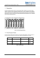
1.1. Power Supply Chassis .................................................................................................................7
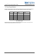
1.2. Power Supply Modules ................................................................................................................8
1.3. Input Power Regulation................................................................................................................9
1.4. Front Panel Indicators................................................................................................................11
1.4.1. Input Power Voltage Indicator....................................................................................................11
1.4.2. Output Power Display ................................................................................................................11
1.4.3. Output Power Indicator ..............................................................................................................11
2. Installation..................................................................................................................................12
2.1. Chassis Mounting ......................................................................................................................12
2.2. Backplane Versions and Module Keying ...................................................................................13
2.2.1. Input Power Terminals: TB1, TB2 (#8 screw terminals) ............................................................13
2.2.2. Output Power Terminals: TB3, TB4 (#6 screw terminals) .........................................................13
2.2.3. Status Connectors: J14, J15......................................................................................................14
2.2.4. Monitor Connector: J13..............................................................................................................14
3. Configuration..............................................................................................................................15
3.1. Current Sharing..........................................................................................................................15
3.2. REGENT Power Supply Load Units...........................................................................................15
3.3. Regent I/O Triplicated Power Distribution..................................................................................15
4. Maintenance ..............................................................................................................................16
5. Specifications.............................................................................................................................17
Figures
Figure 1 Power Supply Assembly.............................................................................................................7
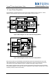
Figure 2 Block Diagram of a dual ac I/O Power Supply Module...............................................................9
Figure 3 Block Diagram of a dual dc I/O Power Supply Module...............................................................9
Figure 4 Power Supply Chassis Front View............................................................................................12
Figure 5 Power Supply Chassis Rear View ............................................................................................12
Tab l e s
Table 1 Chassis Types .............................................................................................................................7
Table 2 Module Types ..............................................................................................................................8
Table 3 Input Power Terminals...............................................................................................................13
Table 4 Output Power Terminals............................................................................................................13
Table 5 Status Connectors .....................................................................................................................14