
Manual

Trusted
TM
Power Supply System T82xx
Issue 9 Mar 06 PD-T82xx 13
Mounting flanges can be attached to either the rear or the front of the chassis. This allows flush
mounting the chassis to a panel or mounting in a 19-inch rack.
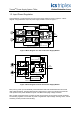
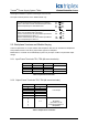
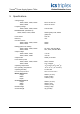
The input crossover patch is on the T8200 chassis only.
Input Crossover Patch configured for no crossover,
source 1 and source 2 are connected to input A and
input B respectively for all modules slots.
6E5 6E6
6E7 6E8
6E3 6E4
6E1 6E2
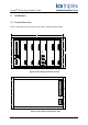
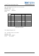
Input Crossover Patch configured to swap source 1 and
source 2 for modules slots 4 through 6.
Source 1 and source 2 are connected to input A and
input B respectively for slots 1-3.
Source 1 and source 2 are connected to input B and
input A respectively for slots 4-6.
2.2. Backplane Versions and Module Keying
Connector placement on ac input modules and backplanes differ from dc modules and backplanes.
This prohibits insertion of the wrong input module type into a backplane.
Module slots in a chassis can be individually keyed to only accept a module of an particular output
voltage.
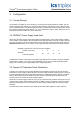
2.2.1. Input Power Terminals: TB1, TB2 (#8 screw terminals)
Terminal No. T8200 T8202 Source
1 N DC- B
2 L DC+
3 N DC- A
4 L DC+
Table 3 Input Power Terminals
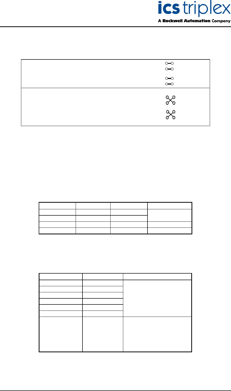
2.2.2. Output Power Terminals: TB3, TB4 (#6 screw terminals)
Terminal No. Module Slot T8200, T8202
12 6
11 5
10 4 + DC Output
9 3
8 2
7 1
6
5
4 1-6 DC Return
3 (terminals 1-6 are
2 Connected together on
1 Backplane)
Table 4 Output Power Terminals
6E
6E5
6E
6E
6E
6E
6E1
6E