TrustedTM PD-T82xx TrustedTM High Integrity Power Supply 110-240V ac and 24V dc Introduction The power supply assembly converts redundant main line voltages of either 110V ac / 240V ac or 24V dc, to +15V dc or +24V dc output power for system and field power requirements.
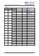
TrustedTM Power Supply System T82xx Issue Record Issue Number Date Revised by 8 Sep 05 J W Clark Format 9 Mar 06 Pete Stock Removed hidden characters Issue 9 Mar 06 Technical Check Authorised by Modification PD-T82xx 2
TrustedTM Power Supply System T82xx This page is intentionally blank Issue 9 Mar 06 PD-T82xx 3
TrustedTM Power Supply System T82xx Table of Contents 1. Description ...................................................................................................................................7 1.1. Power Supply Chassis .................................................................................................................7 1.2. Power Supply Modules ................................................................................................................8 1.3.
TrustedTM Power Supply System T82xx Notice The content of this document is confidential to ICS Triplex Technology Ltd. companies and their partners. It may not be given away, lent, resold, hired out or made available to a third party for any purpose without the written consent of ICS Triplex Technology Ltd. This document contains proprietary information that is protected by copyright. All rights are reserved.
TrustedTM Power Supply System T82xx Revision and Updating Policy All new and revised information pertinent to this document shall be issued by ICS Triplex Technology Ltd. and shall be incorporated into this document in accordance with the enclosed instructions. The change is to be recorded on the Amendment Record of this document.
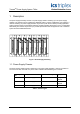
TrustedTM Power Supply System T82xx 1. Description The power supply assembly consists of a power supply chassis containing up to six power supply modules. The chassis may be configured to distribute power in various combinations. For example, a chassis containing six power supply modules may be set up with three modules providing triplicated power for Regent+Plus I/O assemblies and three modules providing field power in a N+1 configuration.
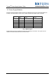
TrustedTM Power Supply System T82xx 1.2. Power Supply Modules The power supply assembly modules are single (if redundant inputs are not required) and dual input, hot swap, user-replaceable ac and dc units. Table 2 identifies the available types of modules. Catalogue No.
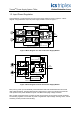
TrustedTM Power Supply System T82xx 1.3. Input Power Regulation A block diagram of a typical dual ac input I/O power supply module is shown in Figure 2. A block diagram of a typical dual dc input I/O power supply module is shown in Figure 3.
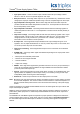
TrustedTM Power Supply System T82xx • • Input power failure - Active low status output. Indicates when the input voltage is below 85V ac or 18V dc. There is a separate signal for each input. • Bulk power failure - Active high status output on ac input modules only. Indicates the dc bulk voltage (PFC output) is outside the specified range. There is a separate signal for each input. • High-temperature warning alarm - Both an active high and active low status output are provided.
TrustedTM Power Supply System T82xx 1.4. Front Panel Indicators The front panel of each I/O power supply module supports three LED indicators detailed in the following sub-paragraphs 1.4.1. Input Power Voltage Indicator Each green INPUT POWER indicator is lit when the associated input (Input A, Input B) is above the lower input voltage threshold. 1.4.2. Output Power Display The 10-segment LED indicator bar displays the approximate output current level percentage (0% 100%) 1.4.3.
TrustedTM Power Supply System T82xx 2. Installation 2.1. Chassis Mounting Figure 4 and Figure 5 show the front and rear views of the power supply chassis. 19" TB3 J1 J2 J3 J5 J6 Input Crossover Patch J14 J15 J4 10.
TrustedTM Power Supply System T82xx Mounting flanges can be attached to either the rear or the front of the chassis. This allows flush mounting the chassis to a panel or mounting in a 19-inch rack. The input crossover patch is on the T8200 chassis only. Input Crossover Patch configured for no crossover, source 1 and source 2 are connected to input A and input B respectively for all modules slots.
TrustedTM Power Supply System T82xx 2.2.3. Status Connectors: J14, J15 Type: 10 pin shrouded header, double row, 0.100 x 0.
TrustedTM Power Supply System T82xx 3. Configuration 3.1. Current Sharing The modules are capable of current sharing by connecting their outputs together in parallel. This can be done external to the chassis or by using a shorting bar that mounts directly to the output terminals on the chassis backplane. This allows separate groups of modules from within a single chassis to have their outputs configured as Single, Dual or N+1.
TrustedTM Power Supply System T82xx 4. Maintenance No periodic maintenance or calibration is required for I/O power supply modules. There are no userreplaceable parts. A failed I/O power supply module can be hot-replaced without disrupting system operations. Main power wiring and I/O power cables (connected to the chassis) are not disturbed during module replacement.
TrustedTM Power Supply System T82xx 5. Specifications Voltage Range T8220, T8223, T8224, T8225 T8222, T8226 85V ac to 264V ac 20V dc to 32V dc Frequency Range T8220, T8223, T8224, T8225 47Hz to 63Hz Inrush Current (120/260V ac) T8220, T8223, T8224, T8225 20/40A (peak) Cold, 35/65A (peak) Hot Power Factor 0.95 min.