
Instruction Manual

Trusted
TM
Power System T823X
Issue 9 Dec 08 PD-T823X 12
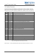
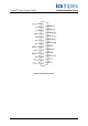
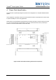
3.4. Interface Connector
The Power Shelf has an optional DSB, 25-pin, female interface connector on the back. The Power
System can be monitored and controlled through this interface, by a Power Controller, using a Power
Shelf Interconnect. AC and DC fail alarms are available from a separate connector on the Power Port.
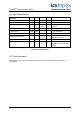
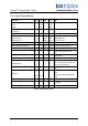
Pin
Number
Signal Name
Description
1 DC Fail_2 DC Fail signal of the second Power Pack
2 A2 I
2
C address bit 2
3 A3 I
2
C address bit 3
4 ON SYNC Not Used
5 SDA I
2
C Serial data bus
6 SCL I
2
C Clock
7 NC No connection
8 On/Off_1 Remote on off control for the first Power Pack - Not Used
9 OTP_1 Fan Fail or Over Temperature signal for the first Power Pack
10 On/Off_2 Remote on off control for the second Power Pack - Not Used
11 V
aux
Not Used
12 DC Fail_1 DC Fail signal of the first Power Pack
13 AC Fail_3 AC Fail signal of the third Power Pack
14 OTP_3 Fan Fail or Over Temperature signal of the third Power Pack
15 DC Fail_3 DC Fail signal of the third Power Pack
16 INT BUS Not used
17 AC Fail_1 AC Fail signal of the first Power Pack
18 On/Off_3 Remote on off control for third Power Pack - Not Used
19 SRTN Signal return and V
aux
return
20 RS- Remote sense for V-
21 OTP_2 Fan Fail or Over Temperature signal of the second Power Pack
22 RS+ Remote sense for V+
23 AC Fail_2 AC Fail signal of the second Power Pack
24 CS A single wire interface for current sharing
25 V- V-
Table 2 Pin Assignment of the Interface Connector
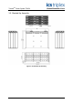
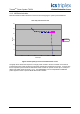
Refer to Figure 4 - 1U Power Shelf Mechanical Outline for the locations of Power Pack 1, 2 and 3.