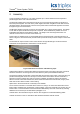
TrustedTM PD-T823X TrustedTM Power System Introduction TM The Trusted Power System is a high density flexible power supply designed to convert main line TM voltages of either 110V or 240Vac. Outputs are either 24Vdc for Trusted product or 28Vdc adjustable field power. TM The Trusted Power System consists of a 1U Power Shelf with mechanical support, containing up to three 750W Power Packs. The Power Packs load share in configurations using one or more Power Shelves.
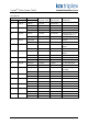
TrustedTM Power System T823X Issue Record Issue Number Date Revised by Technical Check Authorised by 1 July 04 J Bourn G Creech R Cockman 2 Nov 04 J Bourn G Creech R Cockman 3 April 05 J Bourn G Creech R Cockman 4 Sep 05 J W Clark 5 Feb 06 Pete Stock Nick Owens Pete Stock Fault relay details added.
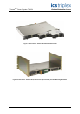
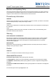
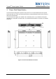
TrustedTM Power System T823X Figure 1 Front View - Power Shelf with Power Packs Figure 2 Rear View - Power Shelf, Power Port (uncovered) and 4U Mounting Brackets Issue 9 Dec 08 PD-T823X 3
TrustedTM Power System T823X Table of Contents 1. Product Range................................................................................................................................8 2. Assembly........................................................................................................................................9 3. Power Shelf Specification.............................................................................................................10 3.1. Input Connector .
TrustedTM Power System T823X Figures Figure 1 Front View - Power Shelf with Power Packs ..............................................................................3 Figure 2 Rear View - Power Shelf, Power Port (uncovered) and 4U Mounting Brackets .........................3 Figure 3 AC Power Connectors and Retaining Clips................................................................................9 Figure 4 1U Power Shelf Mechanical Outline .............................................................
TrustedTM Power System T823X Notice The content of this document is confidential to ICS Triplex Technology Ltd. companies and their partners. It may not be given away, lent, resold, hired out or made available to a third party for any purpose without the written consent of ICS Triplex Technology Ltd. This document contains proprietary information that is protected by copyright. All rights are reserved.
TrustedTM Power System T823X Revision and Updating Policy All new and revised information pertinent to this document shall be issued by ICS Triplex Technology Ltd. and shall be incorporated into this document in accordance with the enclosed instructions. The change is to be recorded on the Amendment Record of this document.
TrustedTM Power System T823X 1. Product Range Catalogue No. Product name Description T8230 Power Shelf 19” x 1U chassis for up to 3 Power Packs. Includes 4U fixing kit, Power Port (with push fit BLZF 3.5/10 connector), mains plugs and retaining clips. T8231 Power Pack 24Vdc 750Watt, universal input, 24Vdc out. T8232 Power Pack 28Vdc 750Watt, universal input, 28Vdc out. T8233 Power Port Plug in diagnostic interface. T8234 Power Controller For live adjustment of output voltage. 19” x 1U.
TrustedTM Power System T823X 2. Assembly A pair of brackets mounted in to a 19” frame supports up to 4 Power Shelves and are required to provide support at the rear of the Power Shelf The brackets supplied mount the equipment by its 19 inch rack ears and provide a box structure to brace the power supplies. The back of the power supplies are fixed using M3.5 screws that are fixed via tapped holes in the Power Shelf.
TrustedTM Power System T823X 3. Power Shelf Specification The Power Shelf is designed to operate as a key element in a complete distributed Power System. This Power Shelf can house up to three Power Packs, provides physical protection and a number of alarm and control features. The Power Shelf can supply up to 1500W of N+1 redundant power or up to 2250W of total power depending on configuration of Power Packs. Four stacked Power Shelves can provide up to 9,000W total power.
TrustedTM Power System T823X 3.1. Input Connector The Power Shelf can be used with any standard global line voltages. The standard AC input connection to the Power Shelf is through three clip retained IEC320 type connectors rated at 10A / 250Vac in Europe/Asia and 15A /120Vac in North America. 3.2. Output Connector The Power Shelf has two terminal blocks for DC output (each with three M4 screws). The V+ and Vare floating with respect to frame GND, either of which can be connected to GND as required. 3.3.
TrustedTM Power System T823X 3.4. Interface Connector The Power Shelf has an optional DSB, 25-pin, female interface connector on the back. The Power System can be monitored and controlled through this interface, by a Power Controller, using a Power Shelf Interconnect. AC and DC fail alarms are available from a separate connector on the Power Port.
TrustedTM Power System T823X Figure 5 Interface Connector Issue 9 Dec 08 PD-T823X 13
TrustedTM Power System T823X 3.5.
TrustedTM Power System T823X 4. Power Pack Specification The Power Pack is specifically designed to operate as an integral part of a complete distributed Power System. A full complement of protection, alarm and control features has been incorporated into the Power Pack to provide versatility for use in many applications. Power Packs can be inserted and removed when live, allowing ‘hot-swap’ of Power Packs (see section 4.7).
TrustedTM Power System T823X 4.1. Power Pack Features 4.1.1. Indicators The Power Pack has two indicators on the front: AC OK: The LED is green if the input voltage is within limits. PWR OK: The LED is green if the Power Pack is healthy and within operating limits. If a fault occurs with the power supply or a fan, the LED is amber. Failure of an internal power pack fan results in shutdown of the output of the power pack. 4.1.2.
TrustedTM Power System T823X 4.1.3. MCB discrimination MCB discrimination studies should be carried out when designing the system power distribution. Power Unit(s) Overload Current Vs Time 300 250 Time / ms 200 1 Power Unit 2 Power Units 150 100 50 0 0 20 40 60 80 100 120 140 Current / Amps Figure 8 Power pack (s) severe overload Current v Time The graph above shows the response of a single power module to severe overloads.
TrustedTM Power System T823X 4.2. Input Specification Parameter Min Typ Max Unit Condition Input voltage 90 264 Vac Input Frequency 47 63 Hz 50 A Full load <25 A No load 0.2 A No load Inrush Current (peak) per pack Input current Power Factor 0.95 Input Leakage Current 0.99 > 50% of full load 1.
TrustedTM Power System T823X 4.4. Efficiency and Power Factor vs. Input Voltage at Full Load Input voltage 90Vac Efficiency (Typical) 78% Power Factor (Typical) 100Vac 79% 0.99 110Vac 80% 0.99 120Vac 81% 0.98 180Vac 82% 0.98 220Vac 83% 0.98 240Vac 83% 0.98 264Vac 84% 0.98 0.99 Table 4 Efficiency and Power Factor vs. Input Voltage at Full Load When using this table to calculate cable feed requirements, allow, at a minimum, an extra 3% for variations between units.
TrustedTM Power System T823X 4.5. Output Specification Parameter Min Typ Max Unit Note VOUT set point: T8231 24 Vdc T8232 28 Vdc Regulation (line, load, temperature & set point) -2 Remote-sense Drop 2 % 0.5 Vdc Measured at remote sense IOUT (rated): T8231 (24VOUT) 0 31.25 Adc 750W maximum T8232 (28VOUT) 0 26.
TrustedTM Power System T823X 4.6. Environmental Characteristics Parameter Min Storage Temperature -40 Operating Temperature (note 1) 0 Typ Altitude Unit Note -85 °C - 60 °C 47 52 dBa 5 95 % -60 3962 m Acoustics Humidity (noncondensing) Max 1. Derate at 1.333%/°C, 45°C to 50°C 2. Derate at 4.667%/°C, 50°C to 60°C Sound Pressure Level at 1m Derated at 2°C/304m above 2438m.
TrustedTM Power System T823X 4.7. Power Pack Hot Replacement 1. Plug in slowly and smoothly. 2. To make sure the first set of pins are contacted. (The AC OK LED will ON) 3. Push to fully contacted.
TrustedTM Power System T823X 5. Power Port 5.1. General Description The Power Port is a supplied accessory and is fitted onto the rear of the Power Shelf. It converts alarm signals produced by the Power Packs and Power Shelf into volt-free alarm contacts for use by the system and enables hot replacement of Power Packs. It consists of a pcb fitted with connectors, relays and miscellaneous electronic components. The shape and size of the Power Port is shown in Figure 11.
TrustedTM Power System T823X 5.2. Circuit Description The circuit is split into four functional sections: supply, dc alarms, ac alarms and jumpers. 5.2.1. Supply The 24V supply is connected to CON3 pins 1 & 6. The supply should be fused close to its source, using a 500mA F rated fuse. It is nevertheless protected by a non-replaceable fuse on the Power Port. The 24V is regulated down to 5V with decoupling provided. The 5V+ is used to supply the low voltage electronics.
TrustedTM Power System T823X 5.2.4. Jumpers There are three jumpers, J1, J2 and J3. 2 J1 and J2 set the Power Shelf address lines for the I C control bus. With J1 and J2 fitted the Pack addresses are 1, 2 and 3, which is the default. Other addresses may be set by removing one or both of J1 and J2, up to 4 shelves worth (or 12 Power Packs).
TrustedTM Power System T823X 5.3. Mechanical 5.3.1. Pin-out CON 1, CON 2 CON 1 on the Power Port connects to the Power Shelf. The pin-out details are shown in Table 2. CON 2 is used to connect to other Power Shelves to current share or to connect to a Power Controller.
TrustedTM Power System T823X 5.3.2. Pin-out CON 3 Pin Description 1 +24V system supply 2 DCFAIL common 3 DCFAIL_3 4 DCFAIL_2 5 DCFAIL_1 6 0V system supply return 7 ACFAIL_1 8 ACFAIL_2 9 ACFAIL_3 10 AC Fail common Table 10 Connector 3 Pin-out CON 3 provides volt-free alarm contacts as detailed in section 5.2.2 and 5.2.3 for use by the system and are made available on a connector for ease of wiring into the system. Fault Relay Technical Specifications Contact Form SPDT Resistive Load 0.
TrustedTM Power System T823X 6. Power Controller The Power Controller is designed to control and monitor the 19” rack mount 1U high Power Shelf units. It is used to address each Power Pack in turn and adjust the respective Power Pack voltage. The Power Controller is a digital system and communicates with the Power Packs by means of a TC323 Power Shelf Interconnect ribbon cable, via the Power Port. The shelf addresses are set using jumpers on the Power Port, as described in paragraph 5.2.4.
TrustedTM Power System T823X 6.1. Power up sequence When a power controller is connected to more than one power shelf, power shelves should have their supplies applied in turn, e.g. power up first shelf (idents 1-3), followed by shelf two (idents 4-6) etc. This ensures that the power pack addresses are not duplicated.
TrustedTM Power System T823X 7. Power Shield If a Power Shelf is not fully populated, Power Shields are used to cover unused spare slots. 8. Power Shelf Interconnect A ribbon cable is required to connect Power Shelves together in order to current share, or to connect shelves to a Power Controller. The supplied ribbon cable has 5 connectors, to allow the maximum of 4 shelves and a Power Controller to be connected.
TrustedTM Power System T823X 9. Power System Specification Voltage Range Input Output 90V ac to 264V ac 24V dc to 28V dc Frequency Range 47Hz to 63Hz Inrush Current 50A Max per Pack Power Factor 0.95 min, 0.