
Owner manual

Trusted
TM
Gateway Adaptor T8173
Issue 01 Feb 10 PD-T8173 3
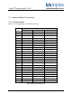
Table of Contents
1.1. Associated Equipment....................................................................................................................6
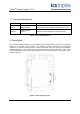
2. Description...........................................................................................................................................6
2.1. Ethernet Ports Connections ...........................................................................................................7
2.2. Keyboard and Mouse Port Connections.........................................................................................7
2.3. Monitor VGA port............................................................................................................................7
3. Installation............................................................................................................................................7
3.1. Gateway Module Connections........................................................................................................8
3.1.1. Connector (SK1)........................................................................................................................8
3.1.2. RJ45 Ethernet Connectors for 10/100BaseT Networks ............................................................9
3.1.3. Connectors for Keyboard and Mouse........................................................................................9
3.1.4. Monitor Connector.....................................................................................................................9
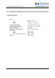
4. Specifications ....................................................................................................................................10
Figures
Figure 1 T8173 Gateway Adaptor.............................................................................................................1
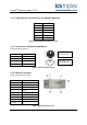
Figure 2 T8173 Internal Layout................................................................................................................6
Tabl es
Table 1 Associated Equipment...............................................................................................................6
Table 2 SK1 Connector pin-out ................................................................................................................8
Table 3 Ethernet RJ45 Connectors Pin-out..............................................................................................9
Table 4 PS/2 Connectors Pin-out .............................................................................................................9
Table 5 VGA Connector Pin-out ...............................................................................................................9