TrustedTM PD-T8160 Trusted TM TMR Interface Introduction The TrustedTM TMR Interface provides the interface between the TrustedTM Controller and the Regent TM and Regent+Plus I/O sub-systems. The Trusted TMR Interface supports the existing Regent I/O Safetybus, and the use of all Regent and Regent+Plus I/O modules as part of an I/O sub-system.
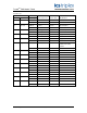
TrustedTM TMR Module T8160 Issue Record Issue Number Date Revised by 8 Oct 05 J W Clark 9 Nov 06 N Owens I Vince P Stock Specifications 10 Feb 08 N Owens A Holgate P Stock Available positions 11 Nov 08 N Owens A Holgate P Stock Supported modules 12 Oct 12 S Blackett N Owens P Stock Supported modules 13 May 13 S Blackett N Owens P Stock Supported modules T3402 and T3462 added Issue 13 May 13 Technical Check Authorised by Modification Format PD-T8160 2
TrustedTM TMR Module T8160 This page is intentionally blank Issue 13 May 13 PD-T8160 3
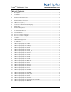
TrustedTM TMR Module T8160 Table of Contents 1. Description ...................................................................................................................................9 2. Installation ..................................................................................................................................10 2.1. Module Insertion/Removal .........................................................................................................10 2.2.
TrustedTM TMR Module T8160 4.22. I/O Complex Equipment ‘SX7441A’ ...........................................................................................44 4.23. I/O Complex Equipment ‘SX7444’ .............................................................................................45 4.24. I/O Complex Equipment ‘DX7444’ .............................................................................................46 4.25. I/O Complex Equipment ‘SX7446’ ...........................................
TrustedTM TMR Module T8160 Figures TM Figure 1 Block Diagram of the Trusted TMR Interface .........................................................................9 Figure 2 Module Polarisation ..................................................................................................................12 Figure 3 Architectural Block Diagram of Processor Sub-System A ........................................................74 TM TMR Processor / Trusted TM TMR Interface Front Panel ................
TrustedTM TMR Module T8160 Notice The content of this document is confidential to ICS Triplex Technology Ltd. companies and their partners. It may not be given away, lent, resold, hired out or made available to a third party for any purpose without the written consent of ICS Triplex Technology Ltd. This document contains proprietary information that is protected by copyright. All rights are reserved.
TrustedTM TMR Module T8160 Revision and Updating Policy All new and revised information pertinent to this document shall be issued by ICS Triplex Technology Ltd. and shall be incorporated into this document in accordance with the enclosed instructions. The change is to be recorded on the Amendment Record of this document.
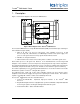
TrustedTM TMR Module T8160 1. Description Figure 1 shows a block diagram of the TrustedTM TMR Interface. Figure 1 Block Diagram of the Trusted TM TMR Interface TM The Trusted TMR Interface is a Triple Modular Redundant (TMR), fault tolerant design containing six fault containment regions (FCR): 1. FCRs A, B, and C are processor sub-systems, each containing a processor, an I/O Processor logic unit, a Bus Interface, an I/O Safetybus interface and a power supply.
TrustedTM TMR Module T8160 2. Installation 2.1. Module Insertion/Removal CAUTION: The module contains static sensitive parts. Static handling precautions must be observed. Specifically ensure that exposed connector pins ARE NOT TOUCHED. Under no circumstances should the module housing BE REMOVED. Before installation, visually inspect the module for damage. Ensure that the module housing appears undamaged and inspect the I/O connector at the back of the module for bent pins.
TrustedTM TMR Module T8160 2.3. Module Pinout Connections 2.3.1. I/O Connector (PL 1) TM This connector provides a number of discrete input and outputs. These provide the Trusted TMR Interface with the connections for the Regent/ Regent+Plus I/O SafetyBus. PL 1 is a 96-way DIN 41612 C type connector. See Table 2 for connector pin-out details.
TrustedTM TMR Module T8160 2.4. TrustedTM Module Polarisation/Keying. All TrustedTM Modules have been keyed to prevent insertion into the wrong position within a chassis. The polarisation comprises two parts. The module and the associated field cable. Each module type has been keyed during manufacture.
TrustedTM TMR Module T8160 3. Application 3.1. Module Management The module is configured automatically by the TrustedTM TMR Processor. Configuration information in the module’s memory is compared with the physical I/O sub-system. Any discrepancies are identified and reported. Changeover between active and standby modules (in dual module configurations) is controlled by the TrustedTM TMR Processor, when the active TrustedTM TMR Interface either fails or is removed 3.2. Communication Busses 3.2.1.
TrustedTM TMR Module T8160 3.3. Isolation All signals exchanged between fault containment regions are protected to prevent the propagation of faults between independently powered regions. The processor and front-panel interface fault containment regions provide isolation for the 24Vdc power feed in addition to the POWER WARNING signal. 3.4. I/O Modules Supported The T8160 interface provides the following support for the Regent+Plus I/O modules.
TrustedTM TMR Module T8160 4. Configuration The creation of a system with an interface between a TrustedTM processor and Regent I/O chassis and modules requires an entry in the System INI Configuration and appropriate complex I/O definitions in the Toolset application I/O Connection Table. The TrustedTM system will support the T8160 in any I/O module slot in the first ten TrustedTM chassis. However, the system configuration tool restricts its placement to the processor chassis.
TrustedTM TMR Module T8160 4.1. I/O Complex Equipment ‘TTMRI’ Description: TrustedTM TMR Interface to Regent equipment (simplex module). OEM PARAMETERS OEM parameter Valid numbers Description TICS_CHASSIS TICS_SLOT 1 – 10 1 – 8 (Chassis 1) 1 – 12 (Expander Chassis) The TICS chassis & slot number where the TMR Interface module is placed. Chassis 1 is recommended for priority operation. CONFIGURATION PHYSICAL MODULE: RACK 1: 1 ANALOGUE Input TMR Interface status.
TrustedTM TMR Module T8160 EXTRA INFORMATION TMR Interface Status word format Bit No. Description 0 TMR Interface Slice A status 1 TMR Interface Slice A status 2 TMR Interface Slice B status 3 TMR Interface Slice B status 4 TMR Interface Slice C status 5 TMR Interface Slice C status 6 Not Used 7 Not Used 8 Not Used 9 Not Used 10 Not Used 11 Active/Standby 12 Educated 13 Impending Module 14 Module online 15 Permissible Slot TMR Interface Slice status information.
TrustedTM TMR Module T8160 4.2. I/O Complex Equipment ‘TTMRI_II’ Description: TrustedTM TMR Interface (dual module). OEM PARAMETERS OEM parameter Valid numbers Description TICS_CHASSIS TICS_SLOT 1 – 10 1 – 8 (Chassis 1) 1 – 12 (Expander Chassis) The TICS chassis & slot number where the first (left) TMR Interface module is placed. Chassis 1 is recommended for priority operation. CONFIGURATION PHYSICAL MODULE: RACK 1: 2 ANALOGUE Inputs TMR Interface status.
TrustedTM TMR Module T8160 EXTRA INFORMATION TMR Interface Status word format Bit No. Description State 0 TMR Interface Slice A 1 TMR Interface Slice A 2 TMR Interface Slice B 3 TMR Interface Slice B 4 TMR Interface Slice C 5 TMR Interface Slice C 6 Not Used 7 Not Used 8 Not Used 9 Not Used 10 Not Used 11 Active/Standby 12 Educated 13 Impending Module 14 Module online 15 Permissible Slot TMR Interface Slice status information. Bit n+1 Bit n See TMR Interface Slice status information.
TrustedTM TMR Module T8160 4.3. I/O Complex Equipment ‘SX7401’ Description: T7401 DC Digital Input Module, 24V dc. The Digital Input Module interfaces 16 discrete field devices into a triplicated I/O Safetybus. Field power for the input is arranged in two 8-point groups. The 24V dc digital input module provides 16 sinking input circuits capable of sensing digital inputs that switch field power ranging from 14V dc to 32V dc. This board definition is for a module used in a simplex configuration.
TrustedTM TMR Module T8160 4.4. I/O Complex Equipment ‘TX7401’ Description: T7401 DC Digital Input Module, 24V dc. The Digital Input Module interfaces 16 discrete field devices into a triplicated I/O Safetybus. Field power for the input is arranged in two 8-point groups. The 24V dc digital input module provides 16 sinking input circuits capable of sensing digital inputs that switch field power ranging from 14V dc to 32V dc. This board definition is for modules used in a triplicated configuration.
TrustedTM TMR Module T8160 4.5. I/O Complex Equipment ‘TX7401_P’ Description: T7401 DC Digital Input Module, 24V dc. The Digital Input Module interfaces 16 discrete field devices into a triplicated I/O Safetybus. Field power for the input is arranged in two 8-point groups. The 24V dc digital input module provides 16 sinking input circuits capable of sensing digital inputs that switch field power ranging from 14V dc to 32V dc.
TrustedTM TMR Module T8160 4.6. I/O Complex Equipment ‘SX7402’ Description: T7402 DC Digital Input Module, 48V dc. The Digital Input Module interfaces 16 discrete field devices into a triplicated I/O Safetybus. Field power for the input is arranged in two 8-point groups. The 48V dc digital input module provides 16 sinking input circuits capable of sensing digital inputs that switch field power ranging from 14V dc to 32V dc. This board definition is for a module used in a simplex configuration.
TrustedTM TMR Module T8160 4.7. I/O Complex Equipment ‘TX7402’ Description: T7402 DC Digital Input Module, 48V dc. The Digital Input Module interfaces 16 discrete field devices into a triplicated I/O Safetybus. Field power for the input is arranged in two 8-point groups. The 48V dc digital input module provides 16 sinking input circuits capable of sensing digital inputs that switch field power ranging from 14V dc to 32V dc. This board definition is for modules used in a triplicated configuration.
TrustedTM TMR Module T8160 4.8. I/O Complex Equipment ‘SX7404’ Description: T7404 AC Digital Input Module 110V ac. The AC Digital Input module provides input senesing for 16 field input switches. The digital inputs are interfaced to the triplicated I/O Safetybus. This board definition is used in a simplex configuration.
TrustedTM TMR Module T8160 4.9. I/O Complex Equipment ‘TX7404’ Description: T7404 AC Digital Input Module 110V ac. The AC Digital Input module provides input sensing for 16 field input switches. The digital inputs are interfaced to the triplicated I/O Safetybus. This board definition is used in a triplicated configuration. The inputs to the modules are voted on a 2-oo-3 basis. The data presented is in unpacked form with each discrepancy having a single BOOLEAN variable.
TrustedTM TMR Module T8160 4.10. I/O Complex Equipment ‘DX7411F’ Description: T7411F Monitored Digital Input Module, 24V dc. The Monitored Digital Input Module interfaces to 16 field input devices. The Type F module connects to field inputs that switch the ‘hot’ side of field power ranging from 15V dc to 80V dc. The module performs complete testing of the input module electronics. This board definition is used in a voted dual 2-oo-2 input configuration.
TrustedTM TMR Module T8160 CONFIGURATION PHYSICAL MODULE: RACK 1: 16 BOOLEAN inputs. Voted states of the two 7411F boards as identified by the OEM parameters. RACK 2: 3 ANALOGUE inputs Channel 1 – Error status. i.e. 1 bit per pair of channels. LSB = first channel. This is set when the corresponding channels of the two boards disagree after the number of milliseconds configured in the OEM parameter MSEC. Channel 2 – Channel Faults (1 bit per channel) for the first module of the pair.
TrustedTM TMR Module T8160 4.11. I/O Complex Equipment ‘SX7411’ Description: T7411 Monitored Digital Input Module, 24V dc. The Monitored Digital Input Module interfaces to 16 field input devices. The module performs line monitoring of the field wiring connections and automatic testing of the input module electronics. The module is designed to operate from field power ranging from 15V dc to 80V dc. This board definition is used in a simplex configuration.
TrustedTM TMR Module T8160 CONFIGURATION PHYSICAL MODULE RACK 1: 16 BOOLEAN inputs Input states of the module as identified by the OEM parameters. RACK 2: 1 ANALOGUE input Channel Faults (1 bit per channel) for the module. 1 - channel ok, 0 – channel fault RACK 3: 1 BOOLEAN input Input reflecting the board status of the module specified. FALSE - board ok, TRUE – board fault Notes: 1. All parameters must be supplied, even for virtual boards. 2.
TrustedTM TMR Module T8160 4.12. I/O Complex Equipment ‘SX7411F’ Description: T7411F Monitored Digital Input Module, 24V dc. The Monitored Digital Input Module interfaces to 16 field input devices. The Type F module connects to field inputs that switch the ‘hot’ side of field power ranging from 15V dc to 80V dc. The module performs complete testing of the input module electronics. This board definition is used in a simplex configuration.
TrustedTM TMR Module T8160 CONFIGURATION PHYSICAL MODULE RACK 1: 16 BOOLEAN inputs Input states of the module as identified by the OEM parameters. RACK 2: 1 ANALOGUE input Channel Faults (1 bit per channel) for the module. 0 - channel ok, 1 - channel fault RACK 3: 1 BOOLEAN input Input reflecting the board status of the module specified. FALSE - board ok, TRUE – board fault Notes: 1. All parameters must be supplied, even for virtual boards. TM 2.
TrustedTM TMR Module T8160 4.13. I/O Complex Equipment ‘SX7418F’ Description: T7418F Monitored Digital Input Module, 120V ac/dc. The Monitored Digital Input Module interfaces to 16 field input devices. The Type F module connects to field inputs that switch the ‘hot’ side of field power ranging from 90 to 150V ac/dc. The module performs complete testing of the input module electronics. This board definition is used in a simplex configuration.
TrustedTM TMR Module T8160 CONFIGURATION PHYSICAL MODULE RACK 1: 16 BOOLEAN inputs Input states of the module as identified by the OEM parameters. RACK 2: 1 ANALOGUE input Channel Faults (1 bit per channel) for the module. 0 - channel ok, 1 - channel fault (channel status will always be 0 for the ac version) RACK 3: 1 BOOLEAN input Input reflecting the board status of the module specified. FALSE – board ok, TRUE – board fault Notes: 1. All parameters must be supplied, even for virtual boards.
TrustedTM TMR Module T8160 4.14. I/O Complex Equipment ‘F7419’ Description: T7419 Fire Detector Input Module. The Fire Detector Input Module occupies one slot in the Regent+Plus I/O chassis and provides 16 line monitored input channels designed to interface to remote fire input devices. This board definition will open a single module. All inputs are presented in unpacked form (Boolean). Channel status is, however, presented packed form. Each channel has a single bit of the variable.
TrustedTM TMR Module T8160 CONFIGURATION PHYSICAL MODULE: RACK 1: 16 BOOLEAN inputs Input states of the module as identified by the OEM parameters. RACK 2: 1 ANALOGUE input Channel faults (I bit per channel) for the module. 0 – channel ok, 1 – channel fault RACK 3 16 BOOLEAN outputs These channels will force the input LEDs. Channel 1 is module channel 1, Channel 16 is module channel 16. Actual input via rack 1 is not affected. TRUE – LED on, FALSE – LED off.
TrustedTM TMR Module T8160 4.15. I/O Complex Equipment ‘SX7420A’ Description: T7420A Analogue Input Module. The Analogue Input module provides high noise immunity analogue to digital conversion of 8 differential or 16 single-ended field input voltages or currents. The digitally converted values are interfaced to the triplicated I/O Safetybus. This board definition is used in a simplex configuration for single-ended inputs.
TrustedTM TMR Module T8160 4.16. I/O Complex Equipment ‘SX7420D’ Description: T7420A Analogue Input Module. The Analogue Input module provides high noise immunity analogue to digital conversion of 8 differential or 16 single-ended field input voltages or currents. The digitally converted values are interfaced to the triplicated I/O Safetybus. This board definition is for differential inputs and is used in a simplex configuration.
TrustedTM TMR Module T8160 4.17. I/O Complex Equipment ‘S7420_PP’ Description: T7420A Analogue Input Module. The Analogue Input module provides high noise immunity analogue to digital conversion of 8 differential or 16 single-ended field input voltages or currents. The digitally converted values are interfaced to the triplicated I/O Safetybus.
TrustedTM TMR Module T8160 4.18. I/O Complex Equipment ‘SX7431’ Description: T7431 Thermocouple Input Equipment. The thermocouple input equipment includes a termination panel/multiplexer assembly and an input module that plugs into, and interfaces with, a triplicated I/O Safetybus. The termination panel/multiplexer provides connection points for 24 thermocouples and is cabled to the plug-in module. The plug-in module provides 24 channel high noise immunity analogue to digital conversion.
TrustedTM TMR Module T8160 4.19. I/O Complex Equipment ‘SX7431A’ Description: T7431 Thermocouple Input Equipment. The thermocouple input equipment includes a termination panel/multiplexer assembly and an input module that plugs into, and interfaces with, a triplicated I/O Safetybus. The termination panel/multiplexer provides connection points for 24 thermocouples and is cabled to the plug-in module. The plug-in module provides 24 channel high noise immunity analogue to digital conversion.
TrustedTM TMR Module T8160 4.20. I/O Complex Equipment ‘SX7431AP and SX7431PP’ Description: T7431A and T7431 Thermocouple Input Equipment. The thermocouple input equipment includes a termination panel/multiplexer assembly and an input module that plugs into, and interfaces with, a triplicated I/O Safetybus. The termination panel/multiplexer provides connection points for 24 thermocouples and is cabled to the plug-in module.
TrustedTM TMR Module T8160 4.21. I/O Complex Equipment ‘DX7441A’ Description: T7441A Digital Output Module, 24V dc. The Digital Output Module provides digitally switched outputs for controlling 16 field loads. The 24V dc digital output circuits are ‘sourcing’ outputs that switch field power ranging from 18V dc to 32V dc. Field power for the outputs is arranged in two isolated groups of 8 points. This board definition is used in a dual module configuration.
TrustedTM TMR Module T8160 4.22. I/O Complex Equipment ‘SX7441A’ Description: T7441A Digital Output Module, 24V dc. The Digital Output Module provides digitally switched outputs for controlling 16 field loads. The 24V dc digital output circuits are ‘sourcing’ outputs that switch field power ranging from 18V dc to 32V dc. Field power for the outputs is arranged in two isolated groups of 8 points. This board definition is used in a simplex configuration.
TrustedTM TMR Module T8160 4.23. I/O Complex Equipment ‘SX7444’ Description: T7444 AC Digital Output Module. The AC Digital Output Module provides digitally switched outputs for controlling 16 field loads. The 110V ac digital output circuits are ‘sourcing’ outputs that switch field power ranging from 90V ac to 130V ac. Field power for the outputs is arranged in two isolated groups of 8 points. This board definition is used in a simplex configuration.
TrustedTM TMR Module T8160 4.24. I/O Complex Equipment ‘DX7444’ Description: T7444 AC Digital Output Module. The AC Digital Output Module provides digitally switched outputs for controlling 16 field loads. The 110V ac digital output circuits are ‘sourcing’ outputs that switch field power ranging from 90V ac to 130V ac. Field power for the outputs is arranged in two isolated groups of 8 points. This board definition is used in a dual configuration.
TrustedTM TMR Module T8160 4.25. I/O Complex Equipment ‘SX7446’ Description: T7446 Relay Output Module. The Relay Output Module provides relay outputs for controlling eight field loads. This board definition is used in a simplex configuration.
TrustedTM TMR Module T8160 4.26. I/O Complex Equipment ‘DX7446’ Description: T7446 Relay Output Module. The Relay Output Module provides relay outputs for controlling eight field loads. This board definition is used in a dual configuration. Each module can be located in any Regent rack or slot.
TrustedTM TMR Module T8160 4.27. I/O Complex Equipment ‘SX7461’ Description: T7461 DC Guarded Digital Output Module 24VDC. The DC Guarded Digital Output Module provides digitally switched outputs for controlling eight field loads. Field power for the outputs is arranged in two triplicated inputs. This board definition is used in a simplex configuration. Product Description reference: PD-7019 Regent+ Guarded 24, 48, 120Vdc.
TrustedTM TMR Module T8160 4.28. I/O Complex Equipment ‘DX7461’ Description: T7461 DC Guarded Digital Output Module 24VDC. The DC Guarded Digital Output Module provides digitally switched outputs for controlling eight field loads. Field power for the outputs is arranged in two triplicated inputs. This board definition is used in a dual configuration. . Each module can be in any Regent rack or slot. All data attached to this definition is unpacked with BOOLEAN variables used.
TrustedTM TMR Module T8160 4.29. I/O Complex Equipment ‘SX7462’ Description: T7462 DC Guarded Digital Output Module 48VDC. The DC Guarded Digital Output Module provides digitally switched outputs for controlling eight field loads. Field power for the outputs is arranged in two triplicated inputs. This board definition is used in a simplex configuration. Product Description reference: PD-7019 Regent+ Guarded 24, 48, 120Vdc.
TrustedTM TMR Module T8160 4.30. I/O Complex Equipment ‘DX7462’ Description: T7462 DC Guarded Digital Output Module 48VDC. The DC Guarded Digital Output Module provides digitally switched outputs for controlling eight field loads. Field power for the outputs is arranged in two triplicated inputs. This board definition is used in a dual configuration. . Each module can be in any Regent rack or slot. All data attached to this definition is unpacked with BOOLEAN variables used.
TrustedTM TMR Module T8160 4.31. I/O Complex Equipment ‘SX7464’ Description: T7464 AC Guarded Digital Output Module 110V ac. The AC Guarded Digital Output Module provides digitally switched outputs for controlling 16 field loads. The 110V ac digital output circuits are ‘sourcing’ outputs that switch field power ranging from 90V ac to 130V ac. Field power for the outputs is arranged in two isolated groups of 8 points. This board definition is used in a simplex configuration.
TrustedTM TMR Module T8160 4.32. I/O Complex Equipment ‘DX7464’ Description: T7464 AC Guarded Digital Output Module 110V ac. The AC Guarded Digital Output Module provides digitally switched outputs for controlling 16 field loads. The 110V ac digital output circuits are ‘sourcing’ outputs that switch field power ranging from 90V ac to 130V ac. Field power for the outputs is arranged in two isolated groups of 8 points. This board definition is used in a dual configuration.
TrustedTM TMR Module T8160 4.33. I/O Complex Equipment ‘SX7480’ Description: T7480 Guarded Analogue Output Module. The Guarded Analogue Output Module provides six 4mA - 20mA current output sources for driving user loads. The outputs are 12-bit D-to-A converted values driven from a triplicated I/O Safetybus interface. The module requires external power from a nominal 24V dc field power source to power the optically isolated analogue field-side circuits. This board definition is for a simplex configuration.
TrustedTM TMR Module T8160 4.34. I/O Complex Equipment ‘SX7481’ Description: T7481 Monitored Guarded Output Module, 24V dc. The Monitored Guarded Output Module provides switching of 18V dc to 36V dc power to 16 field outputs. The outputs are arranged in two groups of 8 outputs, where each group is powered from a common power source. This board definition is for a simplex configuration.
TrustedTM TMR Module T8160 4.35. I/O Complex Equipment ‘DX7481’ Description: T7481 Monitored Guarded Output Module, 24V dc. The Monitored Guarded Output Module provides switching of 18V dc to 36V dc power to 16 field outputs. The outputs are arranged in two groups of 8 outputs, where each group is powered from a common power source. This board definition is for a dual module configuration.
TrustedTM TMR Module T8160 4.36. I/O Complex Equipment ‘DX7481PP’ Description: T7481 Monitored Guarded Output Module, 24V dc. The Monitored Guarded Output Module provides switching of 18V dc to 36V dc power to 16 field outputs. The outputs are arranged in two groups of 8 outputs, where each group is powered from a common power source. This board definition is for a dual module configuration, has packed channel status’ for each board and is recommended for use with medium to high output count systems.
TrustedTM TMR Module T8160 4.37. I/O Complex Equipment ‘SX7481_P’ Description: T7481 Monitored Guarded Output Module, 24V dc. The Monitored Guarded Output Module provides switching of 18V dc to 36V dc power to 16 field outputs. The outputs are arranged in two groups of 8 outputs, where each group is powered from a common power source. This board definition is for a simplex configuration, has packed channel status’ for each board and is recommended for use with medium to high output count systems.
TrustedTM TMR Module T8160 4.38. I/O Complex Equipment ‘SX7484’ Description: T7484 Simplex Monitored Guarded Digital Output Module, 110V ac. The Monitored Guarded Output Module provides switching of 90V ac to 130V ac power to 16 field outputs. The outputs are arranged in two groups of 8 outputs, where each group is powered from a common power source. This board definition is for a simplex configuration.
TrustedTM TMR Module T8160 4.39. I/O Complex Equipment ‘SX7484_P’ Description: T7484 Simplex Monitored Guarded Digital Output Module, 110V ac. The Monitored Guarded Output Module provides switching of 90V ac to 130V ac power to 16 field outputs. The outputs are arranged in two groups of 8 outputs, where each group is powered from a common power source.
TrustedTM TMR Module T8160 4.40. I/O Complex Equipment ‘DX7484’ Description: T7484 Simplex Monitored Guarded Digital Output Module, 110V ac. The Monitored Guarded Output Module provides switching of 90V ac to 130V ac power to 16 field outputs. The outputs are arranged in two groups of 8 outputs, where each group is powered from a common power source. This board definition is for a dual module configuration.
TrustedTM TMR Module T8160 4.41. I/O Complex Equipment ‘DX7484_P’ Description: T7484 Simplex Monitored Guarded Digital Output Module, 110V ac. The Monitored Guarded Output Module provides switching of 90V ac to 130V ac power to 16 field outputs. The outputs are arranged in two groups of 8 outputs, where each group is powered from a common power source.
TrustedTM TMR Module T8160 4.42. I/O Complex Equipment ‘SX7485’ Description: T7485 Isolated Guarded Digital Output Module 24 to 120V ac/dc. The Isolated Guarded Digital Output Module provides digitally switched outputs for controlling eight field loads. The digital output circuits are ‘sourcing’ outputs that switch field power ranging from 24 to 120V ac/dc. This board definition is used in a simplex configuration.
TrustedTM TMR Module T8160 4.43. I/O Complex Equipment ‘DX7485’ Description: T7485 Isolated Guarded Digital Output Module 24 to 120V ac/dc. The Isolated Guarded Digital Output Module provides digitally switched outputs for controlling eight field loads. The digital output circuits are ‘sourcing’ outputs that switch field power ranging from 24 to 120V ac/dc. This board definition is used in a dual configuration.
TrustedTM TMR Module T8160 4.44. I/O Complex Equipment ‘SX7488’ Description: T7488 Monitored Guarded Digital Output Module, 120V dc. The Monitored Guarded Output Module provides switching of 90V ac to 130V dc power to 16 field outputs. The outputs are arranged in two groups of 8 outputs, where each group is powered from a common power source. This board definition is for a simplex module configuration.
TrustedTM TMR Module T8160 4.45. I/O Complex Equipment ‘DX7488’ Description: T7484 Monitored Guarded Digital Output Module, 120V dc. The Monitored Guarded Output Module provides switching of 90V ac to 130V dc power to 16 field outputs. The outputs are arranged in two groups of 8 outputs, where each group is powered from a common power source. This board definition is for a dual module configuration. Each module can be in any Regent rack or slot.
TrustedTM TMR Module T8160 4.46. I/O Complex Equipment ‘M7491’ Description: T7491 Multiplexed I/O Module. The Multiplexed I/O Module occupies one slot in the Regent+Plus I/O chassis and provides two serial communications port interfaces to remote multiplexed digital I/O and addressable loop devices. The module provides an economical interface to inputs and outputs for matrix and mimic displays in fire and gas systems.
TrustedTM TMR Module T8160 4.47. I/O Complex Equipment ‘M7491_IP’ Description: T7491 Multiplexed Input Module. The Multiplexed Input Module occupies one slot in the Regent+Plus I/O chassis and provides two serial communications port interfaces to remote multiplexed digital inputs. This module is used to declare a Matrix Driver Input Unit. All data is presented in packed form.
TrustedTM TMR Module T8160 4.48. I/O Complex Equipment ‘M7491_I’ Description: T7491 Multiplexed Input Module. The Multiplexed Input Module occupies one slot in the Regent+Plus I/O chassis and provides two serial communications port interfaces to remote multiplexed digital inputs and addressable loop devices. This module is used to declare a Matrix Driver Input Unit.
TrustedTM TMR Module T8160 4.49. I/O Complex Equipment ‘M7491_OP’ Description: T7491 Multiplexed Output Module. The Multiplexed Output Module occupies one slot in the Regent+Plus I/O chassis and provides two serial communications port interfaces to remote multiplexed digital outputs. This module is used to declare a Matrix Driver Output Unit. All data is presented in packed form.
TrustedTM TMR Module T8160 Notes: 1. All parameters must be supplied, even for virtual boards. 2. TrustedTM chassis and slot numbers start at 1, Regent+Plus I/O chassis and slot numbers start at 1. 3. Outputs are organised as 8 x 16 bit analogues. Each output requires 2 bits. Bits within the first analogue output are allocated as follows: F7 S7 F6 S6 F5 S5 F4 S4 F3 S3 F2 S2 F1 S1 F0 S0 where bit Fn represents the required flash status for output n and Sn represents the status of output n, i.e.
TrustedTM TMR Module T8160 4.50. I/O Complex Equipment ‘M7491_O’ Description: T7491 Multiplexed Output Module (unpacked state version). The Multiplexed Output Module occupies one slot in the Regent+Plus I/O chassis and provides two serial communications port interfaces to remote multiplexed digital outputs and addressable loop devices. This module is used to declare a Matrix Driver Output Unit.
TrustedTM TMR Module T8160 5. Operation Figure 3 shows the simplified architectural block diagram of a TMR Interface processor sub-system. Figure 3 Architectural Block Diagram of Processor Sub-System A During normal operation, module transition between ‘Active’ and ‘Standby’ modes is under the control TM of the Trusted TMR Processor. TM The module scans the I/O sub-system via the I/O Safetybus and exchanges data with the Trusted TMR Processor.
TrustedTM TMR Module T8160 5.1.1. I/O Processor During each scan cycle, the I/O processor votes input data into its local RAM and transfers it to the shared RAM, making it available to the TrustedTM TMR Processor via the Inter-Module Bus. After TM being processed by the Trusted TMR Processor, output data is placed into the shared RAM and read by the I/O Processor into its local RAM and written to the outputs. The I/O processor also shares in managing the system overhead.
TrustedTM TMR Module T8160 5.2. Front Panel Figure 5 shows the front panel of the TrustedTM TMR Interface. The front panel of the module contains indicators showing overall module health and active/standby status.
TrustedTM TMR Module T8160 5.3. Module Status LEDs The module status LED states and their meanings are described as follows: LED State Description Healthy On Steady Green The Module is healthy. Flashing Processor sub system slice has failed Active On Steady Green Module is in the Active state. Standby On Steady Green Module is in the Standby state. Educated Off Module not educated I/O Healthy On Steady Green Module configuration is valid`.
TrustedTM TMR Module T8160 6. Fault Finding and Maintenance 6.1. Fault Reporting Input module faults are reported to the user through visual indicators (LEDs) on the front panel of the module. Faults are also reported via status variables which may be automatically monitored in the application programs, and external system communications interfaces. There are generally two types of faults that must be remedied by the user; external wiring and module faults.
TrustedTM TMR Module T8160 7. Specifications Voltage Range 20 to 32V dc Heat Dissipation 20W Operating Temperature -5C to 60C (23F to 140F) Non-operating Temperature -25C to 70C (-13 to 158F) Operating Humidity 5 to 95% RH Environmental Specifications Refer to Document 552517 Dimensions Height Width Depth 266mm (10.5ins) 31mm (1.2ins) 303mm (12.0ins) Weight 1.5kg (3.3 lbs.