
Manual

Trusted
TM
Communication Interface Adaptor T8153
Issue 12 Apr 10 PD-T8153 4
Table of Contents
1. Associated Equipment....................................................................................................................7
2. Description......................................................................................................................................8
2.1. RS232 serial ports ..........................................................................................................................9
2.2. RS485 serial ports ..........................................................................................................................9
2.3. Examples........................................................................................................................................9
2.4. RS485 Hints .................................................................................................................................10
2.5. Ethernet ports ...............................................................................................................................10
3. Installation ....................................................................................................................................11
3.1. Communications Interface ...........................................................................................................11
3.1.1. Connector (SK1)...........................................................................................................................11
3.1.2. External Connector Full RS232 bank 1 (J3).................................................................................12
3.1.3. External Connector Partial RS232 bank 2 (J7) ............................................................................12
3.1.4. External Connectors RS485 banks 1 to 4 (J4, J5, and J9 to J14) ...............................................13
3.1.5. External Connectors 10/100BaseT (J6 & J8)...............................................................................13
3.2. Gateway Module...........................................................................................................................14
3.3. Mating Connectors .......................................................................................................................15
4. Specifications ...............................................................................................................................16
Figures
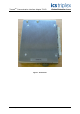
Figure 1 T8153 Photo ...............................................................................................................................3
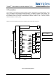
Figure 2 Assembly Layout .......................................................................................................................8
Tabl es
Table 1 Associated Equipment.................................................................................................................7
Table 2 Configuration for multiplexed links...............................................................................................9
Table 3 SK1 Connector pin-out ..............................................................................................................11
Table 4 Connector J3 Pin-out.................................................................................................................12
Table 5 Connector J7 Pin-out.................................................................................................................12
Table 6 Connectors J4,5 and 9-14 Pin-out.............................................................................................13
Table 7 Connectors J6 and J8 Pin-out ...................................................................................................13
Table 8 Mating Connections ...................................................................................................................15