
User Manual


Trusted
TM
Demonstration Unit T8141
Issue 1 Feb 06 PD-T8141 4
Table of Contents
1. Description......................................................................................................................................7
1.1. Communications Ports ...................................................................................................................8
2. Installation ......................................................................................................................................9
3. Operation......................................................................................................................................10
4. Communications Connections......................................................................................................11
4.1. Ethernet Ports...............................................................................................................................11
4.1.1. Ethernet Port 0 .............................................................................................................................12
4.1.2. Ethernet Port 1 .............................................................................................................................12
4.2. Serial Ports ...................................................................................................................................13
5. Specifications ...............................................................................................................................14
Figures
Figure 1 Photo of Demonstration Unit ......................................................................................................3
Figure 2 Front Panel with pre-configured slot locations............................................................................7
Figure 3 Rear View - Internal Layout ........................................................................................................8
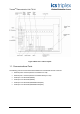
Figure 4 Analogue Input Connection ......................................................................................................10
Figure 5 Ethernet Connections 0 (HUB) and 1 (PC) ..............................................................................11
Figure 6 RJ45 Connections ....................................................................................................................11
Tab l es
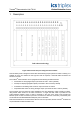
Table 1 Ethernet Port 0 (HUB)................................................................................................................12
Table 2 Ethernet Port 1 (PC) ..................................................................................................................12
Table 3 Serial Port Terminations ............................................................................................................13