TrustedTM PD-T8110B/T8110 Trusted TM TMR Processor Introduction TM TM The Trusted Processor forms the main processing element in a Trusted system control and monitoring facilities. system, providing overall TM A powerful, user-configurable module, the Trusted TMR Processor processes input and output data TM through a variety of analogue and digital I/O modules via a Trusted TMR Communications bus.
TrustedTM TMR Processor T8110B/T8110 Issue Record Issue Number Date Revised by 11 Oct 05 J W Clark 12 Aug 06 N Owens I Vince P Stock Corrections 13 Sep 06 N Owens I Vince P Stock 3.
TrustedTM TMR Processor T8110B/T8110 This page is intentionally blank Issue 18 Feb 08 PD-T8110B/T8110 3
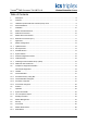
TrustedTM TMR Processor T8110B/T8110 Table of Contents 1. Description ...................................................................................................................................8 1.1. Overview ......................................................................................................................................8 1.2. Hardware Implemented Fault Tolerant (HIFT) Clock...................................................................9 1.3. Power Distribution......
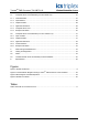
TrustedTM TMR Processor T8110B/T8110 4.6.2. Maintenance Enable Keyswitch .................................................................................................27 4.7. Composite Scan Time Estimation (pre TÜV release 3.5)..........................................................27 4.7.1. Central Modules.........................................................................................................................27 4.7.2. Input Modules ...............................................
TrustedTM TMR Processor T8110B/T8110 Notice The content of this document is confidential to ICS Triplex Technology Ltd. companies and their partners. It may not be given away, lent, resold, hired out or made available to a third party for any purpose without the written consent of ICS Triplex Technology Ltd. This document contains proprietary information that is protected by copyright. All rights are reserved.
TrustedTM TMR Processor T8110B/T8110 Revision and Updating Policy All new and revised information pertinent to this document shall be issued by ICS Triplex Technology Ltd. and shall be incorporated into this document in accordance with the enclosed instructions. The change is to be recorded on the Amendment Record of this document.
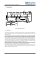
TrustedTM TMR Processor T8110B/T8110 1. Description Figure 1 Module Architecture 1.1. Overview TM The Trusted TMR Processor is a fault tolerant design based on a TMR architecture arranged in a TM lock-step configuration. Figure 1 shows, in simplified terms, the basic structure of the Trusted TMR Processor module.
TrustedTM TMR Processor T8110B/T8110 The functions of the four types of module memory are: EPROM - Holds module bootstrap loader Flash ROM - Stores module firmware and the application program DRAM - Working memory with scaleable capacity NVRAM - Holds data such as event logs and retained program data. Note: The NVRAM provides data retention for up to 10 years. The front panel comprises a Fault Containment Region (FCR D) separate from the other FCRs and contains non-critical simplex functions.
TrustedTM TMR Processor T8110B/T8110 2. Installation 2.1. Module Insertion/Removal CAUTION: The module contains static sensitive parts. Static handling precautions must be observed. Specifically ensure that exposed connector pins ARE NOT TOUCHED. Under no circumstances should the module housing BE REMOVED. Before installation, visually inspect the module for damage. Ensure that the module housing appears undamaged and inspect the I/O connector at the back of the module for bent pins.
TrustedTM TMR Processor T8110B/T8110 2.3. Module Pinout Connections 2.3.1. External I/O Connector (PL1) This connector provides a number of discrete input and outputs. These are provided to allow the TM TM Trusted TMR Processor status to be monitored by external hardware, and to allow the Trusted TMR Processor to monitor the power supply status signals. The connector also provides access to the communications ports and connections for IRIG-B input signals.
TrustedTM TMR Processor T8110B/T8110 3. Application 3.1. Module Configuration TM The Trusted TMR Processor requires no hardware configuration. TM Every Trusted system requires a System INI Configuration file. Details of how to design this are TM given in PD-8082B (Trusted Toolset Suite). The configuration has a processor assigned to the left slot of the processor chassis by default. The System Configurator allows the selection of options on ports, IRIG and system functions.
TrustedTM TMR Processor T8110B/T8110 rim_interval The value is specified in milliseconds. It specifies the minimum amount of time that must elapse TM between polls of Trusted TMR Interface modules. Changes to this value are reflected by the system immediately after the System.INI is loaded. Format : rim_interval=xx Default is 0. pim_interval The value is specified in milliseconds. It specifies the minimum amount of time that must elapse TM between polls of the Trusted Communication Interface modules.
TrustedTM TMR Processor T8110B/T8110 ana_discrep_val The value is specified as 512 counts per volt. It specifies the allowed difference between voltage readings of Analogue Input channel slices before the TMR Processor indicates a channel discrepancy. The Value applied here affects all Analogue Input Modules (Dual & TMR). Changes to this value are not implemented until the TMR Processor is rebooted after the download of the System.ini file. Format : ana_discrep_val=xx Default = 40 (40/512 volts or 78mV).
TrustedTM TMR Processor T8110B/T8110 ao_discrep_val The value is specified as 500 counts per volt. It specifies the allowed difference between voltage readings of Analogue Output channel slices before the TMR Processor indicates a channel discrepancy. This applies to 8480 analogue output modules only. Changes to this value are not implemented until the TMR Processor is rebooted after the download of the System.ini file. Format : ao_discrep_val=xx Default = 250 (250/500 volts or 500mV).
TrustedTM TMR Processor T8110B/T8110 3.1.5. ISaGraf Configuration section IsaGraf processing cycles take priority within the Processor. The IsaGraf Sleep Period is the time TM Communication frame between IsaGraf cycles. It is the period used for scanning the Trusted Interface modules, but it only applies when these are the only modules in the system and no other modules are present.
TrustedTM TMR Processor T8110B/T8110 Typing IRIG S from the MP diagnostics will list the status of the IRIG port. Typing IRIG I from the MP diagnostics will give a detailed list of the IRIG registers.
TrustedTM TMR Processor T8110B/T8110 3.2. Complex I/O Equipment Definition TM All Trusted systems require a processor definition in the I/O Connection Table. Details of how to edit the I/O Connection table are given in PD-8082B. The structure of the definition is given below. 3.2.1. I/O Complex Equipment ‘TTMRP’ TM Description: Trusted TMR Processor. This definition will open a single TMR Processor module. Only one installation is allowed.
TrustedTM TMR Processor T8110B/T8110 RACK 4: [TTMRP_3 – Real time clock input rack] 6 ANALOGUE inputs Channel 1 Year Channel 2 Month Channel 3 Day of month Channel 4 Hours Channel 5 Minutes Channel 6 Seconds If the RTC read channel, Channel 2, of TTMRP_5 is set to TRUE, this input rack is refreshed every cycle to hold the current date and time.
TrustedTM TMR Processor T8110B/T8110 RACK 7: (INFO) 11 INTEGER inputs Channel 1 Channel 2 APPENDIX: Note: Issue 18 Feb 08 Chassis position of AM Slot position of AM 0 – Left 1 – Right Channel 3 Indication of global health of AM 1 – No slice errors 0 – An error has been found Channel 4 Channel 5 Channel 6 Current state of AM Chassis position of SM Slot position of SM 0 – Left 1 – Right Channel 7 Indication of global health of SM 1 – No slice errors 0 – An error has been found Channel 8 Channel 9 Ch
TrustedTM TMR Processor T8110B/T8110 3.3. Inter-Module Bus Each Processor FCR contains a Bus Interface to the Inter-Module Bus. The triplicated Inter-Module TM Bus provides communication interconnection between modules in the Trusted Controller chassis, at a data transfer rate of up to 150Mbaud. The Inter-Module Bus handles the following triplicated signals: Data - 8-bit, bi-directional bus. Control - Bus clocks, module enables and bus direction control.
TrustedTM TMR Processor T8110B/T8110 3.3.4. Front Panel Voting Bus The front panel voting bus provides the following functions: • voted watchdog signal to the front panel for indicating Processor faults. • voted serial data to the front panel for communications, front panel indicators, etc. • protected serial data from the front panel for communications, front panel status, etc. Figure 2 Functional Block Diagram showing TM Trusted TMR Processor Communications 3.4.
TrustedTM TMR Processor T8110B/T8110 4. Operation TM On power-up, the Trusted TMR Processor initialises its local resources and determines their operability. This includes verification of memory, arithmetic and logic units, timers and all fault detection mechanisms. Figure 3 is a block diagram to illustrate module operation. Figure 3 Block Diagram of Module Operation The voter circuits read the input data from the Inter-Module Bus and carry out a continuous 2-oo-3 vote of the data.
TrustedTM TMR Processor T8110B/T8110 4.1.1. System Overheads TM In addition to running application programs, the Trusted TMR Processor takes care of system overheads, (such as background diagnostics), including voter tests, read tests of the EPROMs and read-write tests of the RAM. 4.1.2. On-Line Operator Inputs On-line adjustment of system operating parameters, e.g. set points, loop tuning and time delays, and operator commands, e.g.
TrustedTM TMR Processor T8110B/T8110 4.5. Front Panel TM Figure 4 shows the physical features of the Trusted TMR Processor. The front panel of the TM Trusted TMR Processor has status and diagnostic indicator LEDs, a reset button and a maintenance enable keyswitch.
TrustedTM TMR Processor T8110B/T8110 4.6. Module Status LEDS There are eleven status LEDs on the Processor front panel; three Healthy, one Active, one Standby, one Educated, one Run, one Inhibit, one System Healthy, and two User. The Healthy indicators are controlled directly by each module slice. All LEDs are controlled by the FPU. The FPU receives data from each of the module slices. The FPU performs a 2-oo-3 vote on each data bit from the slices and sets the indicators accordingly.
TrustedTM TMR Processor T8110B/T8110 4.6.1. Reset Button The fault Reset button clears all recorded faults, resets all fault counters and requests all modules to do the same. Fault testing continues, and faults that are still present will be recorded again. The fault reset can also be initiated from the Engineering Workstation by personnel who are authorised by the TM appropriate passwords, to implement maintenance changes to a Trusted System.
TrustedTM TMR Processor T8110B/T8110 The central modules also contribute to the Input Module and Output Module times. The impact to each is factored in on a per-module basis, and is included in the respective calculations as the “Scan Factor”. Module Type No. Installed Time Standby TMR Processor Module x 1 ms TMR Interface Module x 0.81 Communications Interface Module x 1.5 ms1 Scan Factor 4.7.2. Input Modules TM The Input Module time is based on the number of Trusted High Density Input modules.
TrustedTM TMR Processor T8110B/T8110 4.7.4. Application Execution The Application Execution time is based on the estimated size of the application. While actual application size varies greatly based on numerous factors, an estimation of the application size can generally be calculated based on the number of I/O points in a system. The Application Execution time is calculated by adding a constant overhead factor to the total number of I/O modules, then multiplying by a constant time factor No.
TrustedTM TMR Processor T8110B/T8110 4.7.6. Example Calculation TM As an example, consider a simple Trusted system with the following configuration: Part No. Description T8110B TrustedTM TMR Processor TM Qty. Type 1 N/A 2 Central T8151B Trusted T8403 TrustedTM TMR 24Vdc Digital Input Communication 4 Input T8431 TrustedTM TMR Analogue Input 1 Input T8451 TrustedTM TMR 24Vdc Digital Output 2 Output This is a relatively small system with 280 I/O points and 2 communication modules.
TrustedTM TMR Processor T8110B/T8110 4.8. Composite Scan Time Estimation (from TÜV release 3.5) TM The composite scan time for a Trusted system represents the time required to read the input data, solve the application logic, and write the output data. This sequence is repeated cyclically for as long TM as the Trusted system is executing an application. For convenience, the above cyclical sequence is broken down into four discrete elements: input modules, output modules, application and communications.
TrustedTM TMR Processor T8110B/T8110 4.8.3. Application Execution The Application Execution time has a minimal effect on the total scan time. It is based on the processing load of the application. While actual application load varies greatly based on numerous factors, an estimation can generally be calculated based on the number of I/O modules in a system. The Application Execution time is calculated by multiplying the total number of I/O modules by a constant time factor. No.
TrustedTM TMR Processor T8110B/T8110 4.8.5. Example Calculation TM As an example, consider a simple Trusted system with the following configuration: Part No. Description T8110B TrustedTM TMR Processor TM Qty. Type 1 N/A T8151B Trusted 2 N/A T8403 TrustedTM TMR 24Vdc Digital Input 4 Input T8431 TrustedTM TMR Analogue Input 1 Input 2 Output TM T8451 Trusted Communication TMR 24Vdc Digital Output This is a relatively small system with 280 I/O points and 2 communication modules.
TrustedTM TMR Processor T8110B/T8110 5. Fault Finding and Maintenance 5.1. Testing and Diagnostics TM The Trusted TMR Processor provides fault monitoring, self test and diagnostics functions for the TM Trusted TMR processing sub-system. Periodic hardware tests are carried out on the microprocessors, memory management units, clock devices and communications busses. TM The Trusted TMR Processor’s error detection logic is tested periodically to ensure its continued correct operation.
TrustedTM TMR Processor T8110B/T8110 5.3. Transfer between Active and Standby Processor Modules Using the following procedure we have assumed that the standby processor does not have same SYSTEM.INI configuration file as the active processor The user will define the primary processor location as part of the complex equipment definition within the IEC1131 TOOLSET.
TrustedTM TMR Processor T8110B/T8110 6.
TrustedTM TMR Processor T8110B/T8110 This page is intentionally blank Issue 18 Feb 08 PD-T8110B/T8110 37