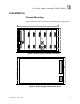
ICS Regent+Plus ® PD-6050 High Integrity Power Supply Assembly 110-240 VAC and 24 VDC (T8060, T8062) Issue 2, March, 06 The power supply assembly (see Figure 1) converts redundant main-line voltages of either 110-240 VAC or 24 VDC to +15 VDC or +24 VDC output power for ICS product power requirements. Figure 1.
I/O Power Supply Assembly (T8060,T8062) Structure The power supply assembly consists of a power supply chassis containing up to six power supply modules. The chassis may be configured to distribute power in various combinations. For example, a chassis containing six power supply modules may be set up with three modules providing triplicated power for Regent+Plus I/O assemblies and three modules providing field power in a N+1 configuration.
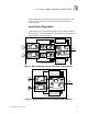
I/O Power Supply Assembly (T8060,T8062) The dual inputs on the AC modules are galvanically isolated from each other. The inputs on the DC modules are diode isolated and share a common return. Input Power Regulation A block diagram of a typical dual AC input I/O power supply module is shown in Figure 2. A block diagram of a typical dual DC input I/O power supply module is shown in Figure 3.
I/O Power Supply Assembly (T8060,T8062) Each primary power input is individually fused and filtered with both standard line filters and metal oxide varistors ( MOVs). The filters attenuate any high-frequency common mode and normal mode noise present in the power distribution system. The MOVs clamp high-voltage transients. Filter, rectifier, and power factor correction circuits convert primary AC input power to bulk DC voltage. The switching regulator converts bulk DC power to regulated DC output voltage.
I/O Power Supply Assembly (T8060,T8062) · - POWER FAIL - Active high status signal that indicates impending loss of output power due to one of the following: Both inputs have indicated power failure Remote off control signal activated Thermal shutdown Output overvoltage · RESET - Active high status signal that is generated a minimum of 10 ms (AC input module) or 0.5 ms (DC input module) after a POWER FAIL signal. RESET remains asserted for 200 ms (minimum) after module power-up.
I/O Power Supply Assembly (T8060,T8062) 6 · Input Power Voltage Indicator Each green INPUT POWER indicator is lighted when the associated input (Input A, Input B) is above the lower input voltage threshold. · Output Power Display The 10-segment LED indicator bar displays the approximate output current level percentage (0 - 100%) · Output Power Indicator The DC Output indicator is lighted when the I/O power supply module's DC output is within tolerance.
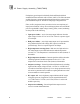
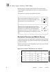
I/O Power Supply Assembly (T8060,T8062) Installation Chassis Mounting Figures 4 and 5 show the front and rear views of the power supply chassis. 19" TB3 J1 J2 J3 J5 J6 Input Crossover Patch J14 J15 J4 10.5" J13 J7 J8 J9 J10 J11 J12 TB1 Figure 4. Power Supply Chassis Front View TB4 TB2 Figure 5.
I/O Power Supply Assembly (T8060,T8062) Mounting flanges can be attached to either the rear or the front of the chassis. This allows flush mounting the chassis to a panel or mounting in a 19-inch rack. The input crossover patch is on the T8200 chassis only. Input Crossover Patch configured for no crossover, source 1 and source 2 are connected to input A and input B respectively for all modules slots. Input Crossover Patch configured to swap source 1 and source 2 for modules slots 4 through 6.
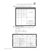
I/O Power Supply Assembly (T8060,T8062) Output Power Terminals: TB3, TB4 (#6 screw terminals) Terminal No. Module Slot 12 6 11 5 10 4 9 3 8 2 7 1 T8200, T8202 + DC Output 6 5 4 1-6 DC Return 3 (terminals 1-6 are 2 Connected together on 1 Backplane) Status Connectors: J14, J15 Type: 10 pin Shrouded Header, Double-Row, 0.100 x 0.100 Centers Mfg.
I/O Power Supply Assembly (T8060,T8062) 8 3 Power Fail 6 Power Fail 9 2 Power Fail 5 Power Fail 10 3 Reset 5 Reset Monitor Connector: J13 Type: 72 pin Edge Connector, 0.125” centerline Mfg.: AMP Mfg. P/N: 1-530844-9 Pin Out: TBD Configuration Current Sharing The modules are capable of current sharing by connecting their outputs together in parallel. This can be done external to the chassis or by using a shorting bar that mounts directly to the output terminals on the chassis backplane.
I/O Power Supply Assembly (T8060,T8062) Calculating the number of load units in your system helps you to determine the number of I/O power supplies your system needs. For economic power distribution, and to avoid overloading individual power supply units, calculate power supply loading when configuring systems. Regent I/O Triplicated Power Distribution A chassis can contain two sets of triple-redundant power supplies for Regent I/O.
I/O Power Supply Assembly (T8060,T8062) Sample Chassis Configurations T8200 Chassis TB3 Two Sets of Triplicated Power and Status to Regent I/O Chassis { 1 { 4 2 3 5 6 7 8 9 10 11 12 IInput Crossover Patch J15 J14 6 6 Source A Source B Two Sets of Triplicated 15 V Regent Power T8201 Chassis TB3 Triplicated Status 15 for Volt Power Regent I/O and Chassis 1 { 2 3 6 4 5 Power and Status for Trusted ICS 6 { 7 4 8 V Power for Field Devices { 12 J15 J14 10 Source A So
I/O Power Supply Assembly (T8060,T8062) Triplicated 15 V Regent and 24 V N+1 Field Power Maintenance No periodic maintenance or calibration is required for I/O power supply modules. There are no user-replaceable parts. A failed I/O power supply module can be hot-replaced without disrupting system operations. Main power wiring and I/O power cables (connected to the chassis) are not disturbed during module replacement.
I/O Power Supply Assembly (T8060,T8062) Specifications Voltage Range T8220, T8223, T8224, T8225 85 to 264 VAC T8222, T8226 20 to 30 VDC Frequency Range T8220, T8223, T8224, T8225 47 to 63 Hz Inrush Current (120/260 Vac) T8220, T8223, T8224, T8225 20/40A (peak) Cold, 35/65A (peak) Hot Power Factor 0.95 min.
I/O Power Supply Assembly (T8060,T8062) Specifications (Continued) Operating Humidity 0 to 95% relative humidity, noncondensing Vibration 10 to 55 Hz: ±0.15mm Shock Operating: 15 g, ½ sine wave, 11 msec Electromagnetic Interference • IEC 801 Part 2 - Electrostatic Discharges Level 3: Contact discharge of 6 kV • IEC 801 Part 3 - Radiated Electromagnetic Fields Level 3: 10 V/M, 27 MHz 500 MHz • IEC 801 Part 4 - Transients and Bursts • IEC 801 Part 5 - Surge Immunity • ANSI/IEEE C37.
I/O Power Supply Assembly (T8060,T8062) Module Weight 16 6.9 lbs (3.