
Manual
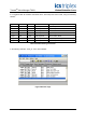
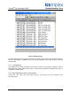
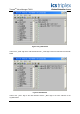
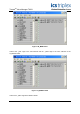
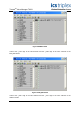
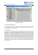
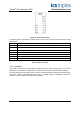
Table Of Contents
- 1. Description
- 2. System Requirements
- 3. OPC Requirements
- 4. Valve Manager Application
- 4.1. Installation
- 4.2. Running the Valve Manager application
- 4.3. Creating a Data Source
- 4.4. Creating a Project
- 4.5. Working with Multiple Projects
- 4.6. Editing a Project
- 4.7. Removing a Project
- 4.8. Adding, Removing, and Renaming Valves
- 4.9. Configuring a Valve Profile
- 4.10. Applying the Same Profile to Multiple Valves
- 4.11. Initiating a Test
- 4.12. Recording Automated Tests and External Events
- 4.13. Clearing Valve Test History
- 4.14. Controlling the Monitor
- 4.15. Project Tree
- 4.16. Main Window
Trusted
TM
Valve Manager T8031
Issue 2 Oct 05 PD-T8031 12
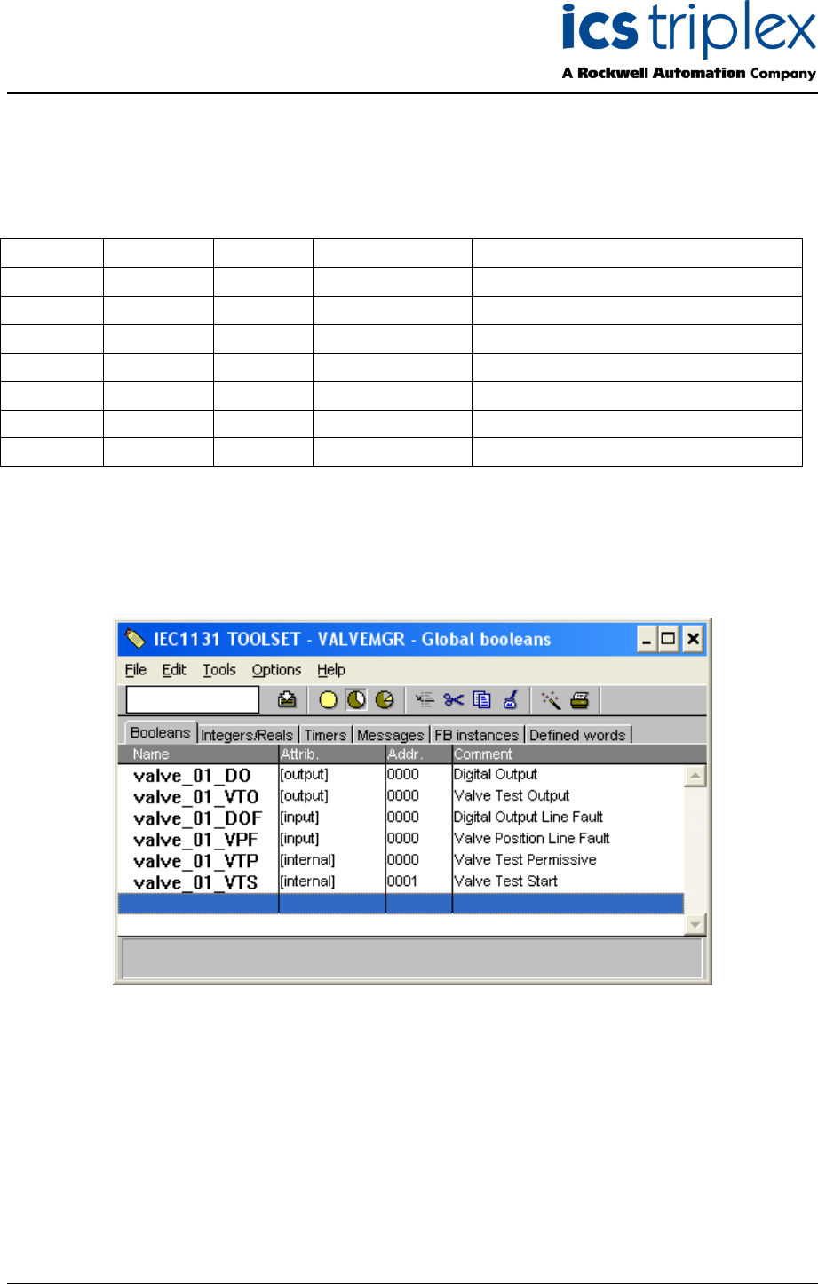
It is suggested that all variables associated with a valve adopt the same format, using the following
suffixes:
Type Attribute Suffix Modbus Access Description
Boolean Output _DO Not Required Digital Output
Boolean Input _DOF Not Required Digital Output Line Fault
Boolean Input _VPF Not Required Valve Position Line Fault
Integer Input _DOS Not Required Digital Output State
Integer Input _VPS Not Required Valve Position State
Integer Input _DOV Not Required Digital Output Voltage
Integer Input _DOI Not Required Digital Output Current
Table 2 Variable Naming Convention
In the following example, “valve_01” is the valve identifier.
Figure 2 Boolean Tags