TrustedTM PD-T8031 TrustedTM Valve Manager Introduction TM The Trusted Valve Manager package is a Windows based software application that configures, TM initiates, collects, processes, and stores valve test information from T8449 – “Trusted TMR 24Vdc Valve Monitor” modules.
TrustedTM Valve Manager T8031 Issue Record Issue Number Date Revised by 2 Oct 05 J W Clark Issue 2 Oct 05 Technical Check Authorised by Modification Format PD-T8031 2
TrustedTM Valve Manager T8031 This page is intentionally blank Issue 2 Oct 05 PD-T8031 3
TrustedTM Valve Manager T8031 Table of Contents 1. Description .................................................................................................................................10 2. System Requirements ...............................................................................................................11 2.1. Required Tags and Tag Naming Convention ............................................................................11 2.1.1. Configuration............................
TrustedTM Valve Manager T8031 4.9. Configuring a Valve Profile ........................................................................................................37 4.9.1. Profile Strings.............................................................................................................................37 4.9.2. State Order ................................................................................................................................38 4.9.3. Profile Editor .............
TrustedTM Valve Manager T8031 Figure 16 Valve Test Permissive Logic ..................................................................................................22 Figure 17 End Time and End State Logic...............................................................................................22 Figure 18 Automated Testing Logic........................................................................................................23 Figure 19 OPC Server Installation .................................
TrustedTM Valve Manager T8031 Table 1 Tag Naming Convention............................................................................................................11 Table 2 Variable Naming Convention .....................................................................................................12 Table 3 Valve Test Values......................................................................................................................
TrustedTM Valve Manager T8031 Notice The content of this document is confidential to ICS Triplex Technology Ltd. companies and their partners. It may not be given away, lent, resold, hired out or made available to a third party for any purpose without the written consent of ICS Triplex Technology Ltd. This document contains proprietary information that is protected by copyright. All rights are reserved.
TrustedTM Valve Manager T8031 Revision and Updating Policy All new and revised information pertinent to this document shall be issued by ICS Triplex Technology Ltd. and shall be incorporated into this document in accordance with the enclosed instructions. The change is to be recorded on the Amendment Record of this document.
TrustedTM Valve Manager T8031 1. Description The Valve Manager application is a tool to help manage the valve test functionality provided by the TM T8449 – “Trusted TMR 24Vdc Valve Monitor” module. The Valve Manager works with one or more TM Trusted systems to simplify valve test configuration, initiate manually valve tests, collect the results, provide additional post-test processing, and save the test information to a database.
TrustedTM Valve Manager T8031 2. System Requirements The Valve Manager requires that certain aspects of the systems that it works with to be configured in a consistent manner. In all such cases, the configuration is limited to the aspects that directly involve valve testing. 2.1. Required Tags and Tag Naming Convention In order to be able to automatically recognize and work with a valve, the Valve Manager requires that certain variables associated with each valve follow a specified naming convention.
TrustedTM Valve Manager T8031 It is suggested that all variables associated with a valve adopt the same format, using the following suffixes: Type Attribute Suffix Modbus Access Description Boolean Output _DO Not Required Digital Output Boolean Input _DOF Not Required Digital Output Line Fault Boolean Input _VPF Not Required Valve Position Line Fault Integer Input _DOS Not Required Digital Output State Integer Input _VPS Not Required Valve Position State Integer Input _DOV
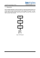
TrustedTM Valve Manager T8031 Figure 3 Analogue Tags The Valve Manager helps to manage valve testing, but it is the T8449 module that actually provides the valve test functionality. Installations that use the Valve Manager must contain at least 1 installed T8449 module. 2.1.1. Configuration The feedback input voltage thresholds for the T8449 module must be properly configured, and the associated valve position states must be known.
TrustedTM Valve Manager T8031 Figure 4 DO_TEST board Connect the “_DOS” tags to the odd channels and the “_VPS” tags to the even channels of the STATE board. Figure 5 STATE board Connect the “_DOV” tags to the odd channels and the “_MXI” tags to the even channels of the AI_MXIN board.
TrustedTM Valve Manager T8031 Figure 6 AI_MXIN board Connect the “_DOI” tags to the odd channels and the “_MXD” tags to the even channels of the CI_MXDAT board. Figure 7 CI_MXDAT board Connect the “_MXO” tags to the MXOUT board.
TrustedTM Valve Manager T8031 Figure 8 MXDAT board Connect the “_ETO” tags to the odd channels and the “_ESO” tags to the even channels of the ETM_EST board. Figure 9 ETM_EST board Connect the “_DOF” tags to the odd channels and the “_VPF” tags to the even channels of the LINEFLT board.
TrustedTM Valve Manager T8031 Figure 10 LINEFLT board 2.2. VTEST Function Block The VTEST function block provides a simplified interface to the valve test functionality of the T8449 – TM “Trusted TMR 24Vdc Valve Monitor” module. The Valve Manager utilizes the VTEST function block to initiate a valve test and record the results. 2.2.1. Operation The VTEST function block initiates a valve test on the rising edge of the VTS input by driving the VTO output TRUE.
TrustedTM Valve Manager T8031 Figure 11 Vtest function block The following table enumerates the possible values of VTM, many of which are derived from the T8449 module itself. Value Description 0 Ready to begin test; Monitoring for change to the Digital Output 1 Test or Change in progress 2 Test or Change complete; VT1…VT5 are valid 3 Test Error 4 Test Aborted 5 Test Failure; VT1…VT5 are valid 6 Function Block is disabled (i.e. VTP is FALSE) Table 3 Valve Test Values 2.2.2.
TrustedTM Valve Manager T8031 Figure 12 Installation Type On the following screen, ensure that only the “Libraries” option is checked before clicking “Next” to proceed with the installation.
TrustedTM Valve Manager T8031 2.2.3. Configuration The VTEST function block must be connected to the appropriate tags in order to function properly. The parameter names match the suffix of the required tags.
TrustedTM Valve Manager T8031 2.3. Additional Application Logic In addition to the required tags and VTEST function block, the application logic requires some minor customization in order to complete the interface to the Valve Manager application. 2.3.1. Valve Test Permissive (VTP) The Valve Test Permissive (or VTP) input on the VTEST function block provides a mechanism for the application or end-user to independently control when a valve test can be performed.
TrustedTM Valve Manager T8031 The following logic would be used to drive the “_VTP” tag to prevent initiating a test: Figure 16 Valve Test Permissive Logic Note the use of the “_VTO” tag as a qualifier for the “_VPS” logic. This is important, as the main purpose of a value test is to change the valve position state. If a test was initiated and the “_VTO” qualifier was not present in the above logic, the test would be aborted as soon as the valve position state changed. 2.3.2.
TrustedTM Valve Manager T8031 Test Error (it sets VTM to 3), then the Valve Manager will reset the VTEST function block by setting VTS to FALSE. This allows the VTEST function block to monitor for any subsequent changes to the valve’s Digital Output. It is anticipated that certain applications will require direct control of the End State and/or End Time values for a given valve.
TrustedTM Valve Manager T8031 3. OPC Requirements TM The Valve Manager application communicates with Trusted Server. TM system through the Trusted OPC 3.1. OPC Run-Time Support The Valve Manager requires the installation of OPC run-time support files. For installation where both the OPC Server and Valve Manager are installed on the same PC, the appropriate OPC components will already be present. If the Valve Manager is to be installed on a different PC, the OPC components must be installed separately.
TrustedTM Valve Manager T8031 On the following screen, ensure that only the “OPC Components” and “Data Access Client” options are checked before clicking “Next” to proceed with the installation. Figure 20 OPC Installation Options It is highly recommended that connectivity to the OPC Server be verified before running the Valve TM Manager. This can be done by running the sample “DA Client” that is available from the Trusted OPC Server installation. 3.2.
TrustedTM Valve Manager T8031 4. Valve Manager Application TM The Trusted Valve Manager package is a Windows based software application that configures, TM initiates, collects, processes, and stores valve test information from T8449 – “Trusted TMR 24Vdc TM Valve Monitor” modules. It uses the Trusted OPC Server to communicate with one or more TM Trusted systems that are configured with T8449 modules, VTEST function blocks, and variables with special suffixes in their tag names. 4.1.
TrustedTM Valve Manager T8031 When the “OK” button is clicked, the Valve Manager will create an empty database and register it as an ODBC data source. A confirmation dialog will then be displayed. Figure 22 Database Creation 4.4. Creating a Project TM The Valve Manager is configured to work with a particular Trusted system by defining a “Project”. A project is created by selecting “Project | New Project” from the main menu.
TrustedTM Valve Manager T8031 4.4.1. Project Name The “Project Name” field is used to describe the project within the Valve Manager application. TM Generally, the name of the Trusted system’s application is used. 4.4.2. OPC Controller The “OPC Controller” field specifies the OPC Server and the specific controller to use for this project. Each project should specify a unique OPC controller. To select the OPC controller, click the “Browse” button. This will bring up the “OPC Server” selection dialog box.
TrustedTM Valve Manager T8031 TM Use the “Browse Controllers” dialog box to select the specific controller for the project. The Trusted OPC Server supports multiple controllers, which can be located by expanding the controller tree. Once the controller for the project is selected, click the “OK” button. Figure 25 Controller Selection Selecting “Cancel” from either the “OPC Server” selection dialog or the “Browse Controllers” dialog will generate an error.
TrustedTM Valve Manager T8031 4.4.4. Data Source The “Data Source” field specifies the ODBC data source (i.e. database) where project information such as configuration and test results will be saved. The same data source can be used by more than one project. To select the data source, click the “Browse” button. This will bring up the “Select Data Source” dialog box. To locate a data source created by the “File | Create Default Database” menu action, switch to the “Machine Data Source” tab.
TrustedTM Valve Manager T8031 4.4.7. Project Notes The “Project Notes” field is a place to enter a description, comments, or operational notes for the project. It is displayed on the “Project” information tab. 4.4.8. Saving the New Project Once all of the fields for a project have been entered, click the “OK” button to create the project. The Valve Manager then connects to the specified data source, creates the necessary tables, then displays an informational dialog box.
TrustedTM Valve Manager T8031 4.4.9. Saving the Valve Manager Configuration Once the tables have been created, the Valve Manager will prompt you to save the current configuration information. The Valve Manager is capable of working with several projects at the same time. Information about these projects as well as other Valve manager settings is stored in this configuration. Enter a name for the configuration file, select a location, then click on “Save”. Figure 28 Saving the Configuration 4.4.10.
TrustedTM Valve Manager T8031 4.5. Working with Multiple Projects The Valve Manager is capable of working with multiple projects at the same time. Simply create a new project and supply the required information. While each project must be associated with a unique OPC controller, it is recommended (but not required) that the all projects use the same data source. 4.6. Editing a Project After a project has been created, you can edit a project by selecting “Project | Edit Project” from the main menu.
TrustedTM Valve Manager T8031 4.7. Removing a Project A project can be removed from the Valve Manager’s configuration by selecting “Project | Delete Project” from the main menu. Before the project is deleted, the Valve Manager will display a dialog box asking for confirmation. Figure 31 Deleting a Project Selecting “Yes” will bring up another dialog box asking if you want to remove the project’s tables from the database. Selecting “Yes” will remove all tables associated with the project.
TrustedTM Valve Manager T8031 4.8. Adding, Removing, and Renaming Valves Each time the Valve Manager connects to the OPC controller for a project, it automatically attempts to discover all of the valves associated with that controller. Any changes made to the controller’s underlying application (such as adding or removing valves) will be automatically detected. When new valves are discovered, a dialog box will be displayed that contains the names of the valves.
TrustedTM Valve Manager T8031 new valves will be display in a separate dialog box, followed by a dialog box for each valve that cannot be located.
TrustedTM Valve Manager T8031 4.9. Configuring a Valve Profile Each valve associated with a project must have a profile. A valve’s profile contains information the Valve Manager uses to initiate tests, apply pass/fail criteria to a test, and to display the test results. To configure a valve’s profile, first select the valve in the Project Tree view. Selecting “Valve | Edit Valve Profile” from the main menu, or clicking on the “Edit Profile” button on the toolbar will bring up the Valve Profile wizard. 4.
TrustedTM Valve Manager T8031 4.9.2. State Order The “State Order” dialog box allows you to configure the order in which the state timing information will be displayed, and which state to include in the display. Typically, the “normal” valve position is at the top of the list and the goal state is at the bottom. States not included in the list will not be displayed, though any timing information collected during a test will be preserved.
TrustedTM Valve Manager T8031 4.9.3. Profile Editor The “Profile Editor” dialog box allows you to configure information that the Valve Manager will use when initiating a test and applying additional pass/fail criteria. You must select the intended “Goal State” for the valve and supply a “Maximum Test Time”. The “Goal State” field corresponds to the _EST” variable in the application and is used to indicate the desired valve position when a test is initiated.
TrustedTM Valve Manager T8031 4.10. Applying the Same Profile to Multiple Valves It is possible to apply the same profile to multiple valves. To do this, first select a valve with the desired profile. Right click on that valve to bring up a menu and select “Copy Valve Profile”. Now select the valve to which you want to apply the profile, right-click on it, and then select “Paste Valve Profile”. Once the profile has been pasted, it can be customized specifically for that valve. 4.11.
TrustedTM Valve Manager T8031 In addition to the “Valve Test” dialog, the progress of a test can be observed in the “Monitor Status” view. Figure 41 Valve Test Progress 4.12. Recording Automated Tests and External Events The Valve Manager continuously monitors all valves in all projects for their current status and activity.
TrustedTM Valve Manager T8031 4.14. Controlling the Monitor The Monitor is responsible for communicating with the OPC controllers through one or more OPC servers. When the Monitor is not running, the Valve Manager cannot discover new or missing valves, report valve status, initiate tests, or record the results of an automated test or external event. However, the Valve Manager can still display information about a projects and valves, including information in the “Last Test” and “History Table” views. 4.
TrustedTM Valve Manager T8031 You can specify how often the Monitor polls each OPC controller for valve status information. Specify the length of time in milliseconds between each poll in the “Update data every” field. The minimum update time is 100 milliseconds, and the maximum is 5000 milliseconds. The value specified in the “Monitor Window” field determines how much information is preserved in the Monitor Status window before it is discarded.
TrustedTM Valve Manager T8031 4.16. Main Window The main window displays detail information based on the current selection in the “Project Tree” view. When a project is selected, only the “Project” view will be displayed. When a valve is selected, the “Project”, “Last Test”, “Profile”, and “History Table” views can be displayed. The contents on the main window can be changed by simply clicking on the appropriate tab for the desired view. 4.16.1.
TrustedTM Valve Manager T8031 4.16.2. Last Test View The Last Test view displays information about the last recorded test for the selected valve. The view includes the date and time the test information was collected, the result, the recorded Goal State, the recorded Maximum Test Time, and a table showing each of the transition times included in the valve’s profile in the prescribed order.
TrustedTM Valve Manager T8031 The overall “Result” field for the test and the individual “Result” fields in the transition time table will turn red when a failure is being reported. Additionally, the text below the overall “Result” field will describe the type of failure.
TrustedTM Valve Manager T8031 4.16.3. Profile View The Profile view displays information about the selected valve’s profile. The view includes the Goal State, Maximum Test Time, and any threshold minimum and maximum values.
TrustedTM Valve Manager T8031 History Table The History Table view displays information about all of the recorded tests for the selected valve in a tabular format. The “Result” field indicates the overall test result as in the Last Test view, however any transition times that did not pass the threshold minimum or maximum times as defined in the valve’s profile will be red.
TrustedTM Valve Manager T8031 This page is intentionally blank Issue 2 Oct 05 PD-T8031 49