TrustedTM PD-T8019 TrustedTM Process Control Algorithm Software Package Introduction TM The system architecture of the Trusted is intended to cover as large a cross section of control and interlock applications as is possible. The control algorithms detailed in this Product Description are primarily intended to support the limited process control capabilities required for Floating Production, Storage and Offloading (FPSO) installations.
TrustedTM Process Control Algorithms T8019 Issue Record Issue Number Date Revised by 6 Oct 05 J W Clark 7 Dec 06 N Owens I Vince P Stock Example PID loop 8 Sep 07 N Owens I Vince P Stock Corrections Issue 8 Sep 07 Technical Check Authorised by Modification Format PD-T8019 2
TrustedTM Process Control Algorithms T8019 This page is intentionally blank Issue 8 Sep 07 PD-T8019 3
TrustedTM Process Control Algorithms T8019 Table of Contents 1. Description ...................................................................................................................................7 1.1. Functions .....................................................................................................................................8 1.1.1. Square Root Extraction................................................................................................................8 1.
TrustedTM Process Control Algorithms T8019 Notice The content of this document is confidential to ICS Triplex Technology Ltd. companies and their partners. It may not be given away, lent, resold, hired out or made available to a third party for any purpose without the written consent of ICS Triplex Technology Ltd. This document contains proprietary information that is protected by copyright. All rights are reserved.
TrustedTM Process Control Algorithms T8019 Revision and Updating Policy All new and revised information pertinent to this document shall be issued by ICS Triplex Technology Ltd. and shall be incorporated into this document in accordance with the enclosed instructions. The change is to be recorded on the Amendment Record of this document.
TrustedTM Process Control Algorithms T8019 1. Description Several of the basic control algorithms may generate error conditions at run-time as all function parameters are variable. This may result in reversed parameters, e.g. max < min, overflow and underflow conditions, divide by zero errors, etc. For each function, the required output under these conditions is defined and error counters are incremented.
TrustedTM Process Control Algorithms T8019 1.1. Functions 1.1.1. Square Root Extraction PV SQRTX OUT IPMAX IPMIN The Process Variable (PV) is scaled to a value 0…1 according to maximum input value (IPMAX) and minimum input value (IPMIN). Out of range values will result in the value being clamped to the range, i.e. a value greater than maximum input will use the IPMAX value, similarly a value below the minimum will use the IPMIN value.
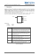
TrustedTM Process Control Algorithms T8019 1.2. BCD Translation IP0 BCD IP1 IP2 OUT IP3 M N The BCD translation function requires the 4-bit BCD value represented as 4 Boolean parameters (IP0, IP1, IP2, and IP3), IP0 being the least significant bit, IP3 the most significant bit. All four inputs must be defined; inputs not required for specific application must be set to FALSE. M and N are of type integer. M specifies the value multiplier and must be a power of 10, i.e. 1, 10, 100, etc.
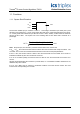
TrustedTM Process Control Algorithms T8019 1.3. Analogue Select SEL R_SEL OUT PV1 PV2 The process variables (PV1 and PV2) and the output (OUT) must all be of type REAL1. The select signal (SEL) is of type BOOLEAN. When SEL is FALSE, PV1 is copied to the output; when SEL is TRUE, PV2 is copied to the output. if SEL Set OUT = PV2 else Set OUT = PV1 end if Out is finite if, and only if, the selected PV1 or PV2 is finite. 1.4.
TrustedTM Process Control Algorithms T8019 1.5. Drum Level Control PC_DRUM PP OUT LV This function is to provide the pressure compensated drum level. PP is the differential pressure, and LV is the level in percentage of full-scale, the output (OUT) is return as a value 0 to 100%. PP, LV and OUT are all of type REAL. The function additionally to compensates for the reverse acting output of the level input (increasing PP value of decreasing differential pressure). OUT = (5.43 × 10 3 × P) LV 0.88 (0.
TrustedTM Process Control Algorithms T8019 2. Function Blocks 2.1. Analogue Scaling PV SCALE IPMAX OUT IPMIN LIMIT OUTMAX OUTMIN The scale function linearly scales the input value (PV) according to the low input (IPMIN), high input (IPMAX), low output (OUTMIN) and high output (OUTMAX) values. The input value is clamped to the range IPMIN to IPMAX. I.e. a PV value less than IPMIN results in the IPMIN value being used, similarly a value greater than IPMAX results in the IPMAX value being used).
TrustedTM Process Control Algorithms T8019 2.2. Analogue Value Clamping IPMIN CLAMP PV OUT LIMIT IPMAX The process variable (PV), IPMAX, IPMIN and OUT values are all of type REAL2. The output value (OUT) is clamped to the range specified by IPMIN and IPMAX. The LIMIT output, which is of the type Boolean, is set to TRUE if the clamp is in operation, i.e. LIMIT = IPMIN>PV>IPMAX.
TrustedTM Process Control Algorithms T8019 2.4. High Value Select PV1 HVS OUT SEL PV2 The process variables (PV1 and PV2) and the output (OUT) are all REAL4. The output (OUT) is set to the higher process variable value. OUT = MAX(PV1, PV2 ) The selected output (SEL) indicates which of the process variables is being used to generate OUT. SEL is of type Boolean, and is FALSE if using PV1 and TRUE if using PV2.
TrustedTM Process Control Algorithms T8019 2.6. Proportional PID Function NOTE The PID_II function block has been superseded by the IPID function block, which provides incremental PID and enhanced functions. All new strategies should use IPID. PID_II is retained for compatibility, but may be replaced in an application by IPID if desired. A PID is a process regulator. Using the feedback concept, an output is regulated according to the difference between its current value (PV) and its required value (SP).
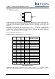
TrustedTM Process Control Algorithms T8019 The figure 1 below gives a simplified overview of the PID function: 1 T Integral + SP + e Error S Proportional Kp Xout + - d K P TD dt PV Derivative Figure 1 PID Function At entry the error S is calculated as the difference between the set-point (SP) and the process variable (PV). This error value is used in the calculation of the proportional and integral terms. The derivative term is derived from PV as shown.
TrustedTM Process Control Algorithms T8019 2.7. Incremental PID Function A PID is a process regulator. Using the feedback concept, an output is regulated according to the difference between its current value (PV) and its required value (SP). The IPID function block is an improved version of the PID_II block with incremental calculation, derivative term switch for PV or error, and a derivative term filter. The IPID block is recommended for all new applications.
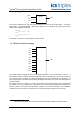
TrustedTM Process Control Algorithms T8019 The figure below gives an overview of the IPID function: 1 Y XOUT T + + Integral S d/dt (Error) + Proportional Derivative Kp KpTS/TI SP + X 2 dS d d/dt S Filter -t/W d/dt dPV d/dt 2 d PV DERR Switch PV 1-e W KPTD/TS Tdf Figure 2 IPID Function The calculation is performed one step into the derivative and is then integrated back for the real output.
TrustedTM Process Control Algorithms T8019 2.8. Deviation Alarm PV DEV_AL SP DEVHI DEVUS DEVLO DEVDS The deviation alarm function block takes the current process variable (PV) and set-point (SP), together with the up-scale and down-scale deviation between the PV and SP (DEVUS and DEVDS respectively). PV, SP, DEVUS and DEVDS are of type REAL, both outputs (DEVHI and DEVLO) are of type Boolean.
TrustedTM Process Control Algorithms T8019 2.10. Time Averaged Value PV T_AVG Tp OUT Ts EN The average function calculates the average process variable (PV) value over the specified period (Tp). The Ts specifies the minimum interval between samples. If the sample period is less than the elapsed period between application program scans, Ts will be the application scan time. PV and OUT are of type REAL; Tp and Ts are of type TIMER.
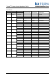
TrustedTM Process Control Algorithms T8019 Example: T_AVG PV 250ms OUT 20ms T (ms) 350 390 432 475 521 565 607 650 690 732 777 821 PV 23.5 15.46 10.01 56.03 58.61 90.17 85.68 84.56 18.09 95.94 75.66 49.38 Ts (ms) 46 40 42 43 46 44 42 43 40 42 45 44 % of Tp 103.2 102.4 101.6 102.8 102.8 104.4 102.8 104.0 103.2 102.8 102.4 102.4 OUT 23.50 22.87 21.09 22.71 28.76 37.26 48.00 58.53 64.87 68.91 73.96 71.
TrustedTM Process Control Algorithms T8019 2.11. Rate of Change Detection Error! Objects cannot be created from editing field codes. The Rate of Change Detection function requires 4 parameters: the process variable to be monitored (PV), the sample interval (Ts), the maximum rate of change parameter (R), and rate of change hysteresis (H). The function detects when the rate of increase or decrease of the process variable (PV) has exceeded the defined limit R.
TrustedTM Process Control Algorithms T8019 Parameters PV, R and H must be finite, i.e. not ±infinities or NaNs. Behaviour is not defined for any other values. If negative values are specified for R or H, their ABS value will be used and the “param” error counter will be incremented. The function must record the sample time for the previous input value and calculate the rate of input value change for the actual elapsed period.
TrustedTM Process Control Algorithms T8019 2.12. Analogue Value Slew PV SLEW OUT RATE The analogue value slew function limits the rate of change of the output value (OUT) to the maximum specified by the RATE input. On initialisation, OUT is set to PV. Changes in the input (PV) will be tracked by the output with the maximum rate of change. If the rate of change of PV is less than the maximum rate, the output will immediately follow the input.
TrustedTM Process Control Algorithms T8019 3. Other Functions 3.1. Lead/Lag Control The lead/lag facility will be provided using the high value select and low value select functions to select the set-point values to be used for the fuel and airflow PID functions. The Lead/Lag is not a function or function block in its own right; this paragraph illustrates the use of the previously defined high value select and low value select functions to provide the required lead/lag control function.
TrustedTM Process Control Algorithms T8019 4. Sample Application Program A sample application program using selected Process Control Algorithms to implement a simple PID loop is shown in Figure 3. Note that many of the input parameters to the ipid function block will usually be program constants, and the extra outputs are not necessary for a single loop. The mantrk blocks allow read/write control of setpoint and output.
TrustedTM Process Control Algorithms T8019 This page is intentionally blank Issue 8 Sep 07 PD-T8019 27