
Instruction Manual


Trusted
TM
Communication Software Package T8017
Issue 10 Mar 08 PD-T8017 30
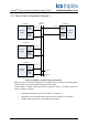
2.4. Peer to Peer Configuration Example 2
Figure 13 shows an example configuration for a system using 4 controllers connected together
u
sing one peer to peer network with dual physical network paths, but this time with multicast
data.
In this example, Controller 4 will be the master of network 1 subnet 1. Controller 1 will be the
master of network 1 subnet 2.
• 16 digital points will be sent from controller 3 to controllers 1, 2 & 4 via a multicast
configuration.
• 16 analogue points will be sent from controller 1 to controller 2.
• A separate set of 16 analogue values will be sent from controller 1 to controller 3.
• 16 digital values will be sent from controller 2 to controller 4.
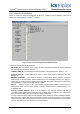
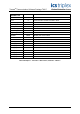
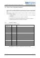
2.4.1. Controller 1 settings
Dual Peer to Peer Net Control, network 1 subnet 1.
dxpnc40 –
CONTROL rack
Value Comment
CHASSIS 1 Communication module located in chassis 1.
SLOT 7 Communication module is located in slot 7.
NETWORK_ID 1 Network 1
SUBNET_ID 1 Subnet 1
PEER_ID 1 Identity of this controller.
RESPONSE_TMO 0 Default
REFRESH_TMO 2000 Default
TX_DATA_TMO 500 Default
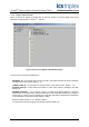
Variable 1 TRUE Enable Peer to on this subnet.
Variable 2 FALSE This is a slave connection.
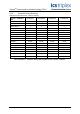
PEERS_1 rack
PEER_IP_01 10.10.1.1 Controller 1, network 1, subnet 1
PEER_IP_02 10.10.1.2 Controller 2, network 1, subnet 1
PEER_IP_03 10.10.1.3 Controller 3, network 1, subnet 1
PEER_IP_04 10.10.1.4 Controller 4, network 1, subnet 1
PEER_IP_05 239.255.1.1 Multicast address
Table 7 Example 2 - Controller 1 Settings Control, network 1 subnet 1