TrustedTM PD-T8017 TrustedTM Peer to Peer Communications Software Package Introduction TM TM Trusted Peer to Peer Communications is provided by the Trusted Communications Interface module (T8150/T8151/T8151B) for the interchange of safety and non-safety information between TM TM Trusted Controllers. Up to four Trusted Communications Interface modules may be fitted in each TM Trusted Controller.
TrustedTM Communication Software Package T8017 Issue Record Issue Number Date Revised by 6 Oct 05 J W Clark Format 7 Jan 06 N Owens Release 3.
TrustedTM Communication Software Package T8017 Table of Contents 1. Peer Network..................................................................................................................................8 1.1. Theory of Operation........................................................................................................................9 1.1.1. Communications Cycle...................................................................................................................9 1.1.
TrustedTM Communication Software Package T8017 Figure 9 Input Board Status Display .......................................................................................................20 Figure 10 Input Board Control Display....................................................................................................21 Figure 11 Peer to Peer Analogue Output Board Display ........................................................................22 Figure 12 Peer to Peer Digital Output Board Display ...
TrustedTM Communication Software Package T8017 Tables Table 1 Example 1 - Controller 1 Net Control, network 1 subnet 1. .......................................................25 Table 2 Example 1 - Controller 1 Net Control, network 1 subnet 2. .......................................................26 Table 3 Example 1 - Controller Setting Summary Net Control, network 1 subnet 1...............................27 Table 4 Example 1 - Controller Setting Summary Net Control, network 1 subnet 2...................
TrustedTM Communication Software Package T8017 Notice The content of this document is confidential to ICS Triplex Technology Ltd. companies and their partners. It may not be given away, lent, resold, hired out or made available to a third party for any purpose without the written consent of ICS Triplex Technology Ltd. This document contains proprietary information that is protected by copyright. All rights are reserved.
TrustedTM Communication Software Package T8017 Revision and Updating Policy All new and revised information pertinent to this document shall be issued by ICS Triplex Technology Ltd. and shall be incorporated into this document in accordance with the enclosed instructions. The change is to be recorded on the Amendment Record of this document.
TrustedTM Communication Software Package T8017 1. Peer Network TM The Peer Network provides communication of safety data between up to forty Trusted systems per peer network. The data can be transferred between individual systems or from one system to several systems at the same time using multicasting. TM A peer network consists of one or more Ethernet networks connecting together a set of Trusted systems to enable safety data to be passed between them.
TrustedTM Communication Software Package T8017 1.1. Theory of Operation Peer communications interaction is Master/Slave which provides deterministic behaviour. Each peer TM communications subnet requires one Trusted system to act as the master for the subnet and up to TM thirty-nine Trusted systems participating as slaves. If redundant masters are required so that a subnet remains operational if the master peer goes offline, then another peer may be permanently set as master.
TrustedTM Communication Software Package T8017 1.1.2. Input Data When the system receives peer input data, it is validated before it is passed on to the application program for use. The system monitors the refreshing of input data. If fresh input data is received within the time-out period, the input refresh status bit on the input board is set to true.
TrustedTM Communication Software Package T8017 2. Programming Information TM The Trusted communications interface modules are selected and assigned to peer communications using the I/O Configuration Editor at the Engineering Workstation (EWS) as described in PD-8082. It should be noted that the (OEM) parameters set up on all board / rack definitions cannot be changed online. General information relating to configuring the modules is detailed below. 2.1.
TrustedTM Communication Software Package T8017 Figure 3 shows the display associated with the Peer Subnet Control board CONTROL rack. Figure 3 Peer Subnet Control board CONTROL rack The user must enter data as detailed below: CHASSIS – Logical chassis where the communication interface is installed. Range 1 - 29. SLOT – this is the slot where the communications interface is installed. Range 1 – 12. NETWORK_ID - Peer network number supported by this controller. Range 1 – 8.
TrustedTM Communication Software Package T8017 Figure 4 shows a display of one of the four peer IP and status racks on the Peer Subnet Control board. Figure 4 Peer Subnet Control board PEERS rack The status rack contains ten IP addresses and ten status bits which indicate the status of the peers on the network. PEER_IP_01 to 10 – IP address of peers with PEER_IDs of 1 to 10 in the subnet.
TrustedTM Communication Software Package T8017 2.2. Peer to Peer Data Boards There are four different peer input boards (two analogue and two digital) that can be selected to ensure that the optimum communication packet size can be used for the application. Each input board has a corresponding output board that must be of the same type and channel quantity. There are two versions of the analogue data boards, a 16 channel version and a 128 channel version. Both are configured the same.
TrustedTM Communication Software Package T8017 2.2.1. Analogue Input Boards Figure 5 shows the data rack display associated with an IEC1131 Toolset 16 channel analogue input TM board selected for incoming data to a Trusted controller. Figure 5 Peer to Peer Input Board Display The user must enter data as detailed below. NETWORK_ID – The network that is carrying the data. Data will be received via all peer controllers that share this network identity. Range 1 – 8.
TrustedTM Communication Software Package T8017 Analogue variable inputs 1 to 16 – Analogue values received from the corresponding channel of the selected output board in the sending system. The values are 32 bit and will assume either a 32 bit signed integer format or 32 bit real format depending on the variable to which it is connected. Both the specific input channel and its corresponding output channel must be connected to the same variable type.
TrustedTM Communication Software Package T8017 Figure 6 shows a display of the refresh status rack of the associated analogue input board. Figure 6 Input Board Status Display Variable 1: TRUE = Input data is valid, i.e. refreshed within REFRESH_TMO Variable 2-9: TRUE = Data has been refreshed within REFRESH_TMO by subnet 1-8, respectively. This status is intended for detection of latent faults within a redundant network. The data is delivered over all available programmed subnets simultaneously.
TrustedTM Communication Software Package T8017 Figure 7 shows a display of the control rack of the associated analogue input board. Figure 7 Input Board Control Display This rack controls the whether the input values hold last state if refresh timer expires or go to 0. Variable 1: FALSE = Force data to the fail safe state when data is invalid. TRUE = Allow previous data to persist when data is invalid.
TrustedTM Communication Software Package T8017 2.2.2. Digital Input Boards Figure 8 shows the data rack display associated with an IEC1131 Toolset 16 channel digital input TM board selected for incoming data to a Trusted controller. Figure 8 Peer to Peer Input Data Rack Display The user must enter data as detailed below: NETWORK_ID – The network that is carrying the data. Data will be received via all peer controllers that share this network identity. Range 1 – 8.
TrustedTM Communication Software Package T8017 Figure 9 shows a display of the refresh status rack of the associated digital input board. Figure 9 Input Board Status Display Variable 1: TRUE = Input data is valid, i.e. refreshed within REFRESH_TMO Variable 2-9: TRUE = Data has been refreshed within REFRESH_TMO by subnet 1-8, respectively. This status is intended for detection of latent faults within a redundant network. The data is delivered over all available programmed subnets simultaneously.
TrustedTM Communication Software Package T8017 Figure 10 shows a display of the control rack of the associated digital input board. Figure 10 Input Board Control Display This rack controls whether the input values hold last state if refresh timer expires or go to FALSE. Variable 1: FALSE = Force data to RACK 1:FS_VALUE when data is invalid. TRUE = Allow previous data to persist when data is invalid.
TrustedTM Communication Software Package T8017 2.2.3. Analogue Output Boards Figure 11 shows the display associated with an IEC1131 Toolset 16 channel analogue output board TM selected for outgoing data to a Trusted controller. Figure 11 Peer to Peer Analogue Output Board Display The user must enter data as detailed below: NETWORK_ID – The network that is carrying the data. Data will be received via all peer controllers that share this network identity. Range 1 – 8.
TrustedTM Communication Software Package T8017 2.2.4. Digital Output Boards Figure 12 shows the display associated with an IEC1131 Toolset 16 channel digital output board TM selected for outgoing data to a Trusted controller. Figure 12 Peer to Peer Digital Output Board Display The user must enter data as detailed below: NETWORK_ID – The network that is carrying the data. Data will be received via all peer controllers that share this network identity. Range 1 – 8.
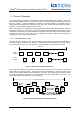
TrustedTM Communication Software Package T8017 2.3. Peer to Peer Configuration Example 1 Controller 1 Processor Module Comm Interface Module Peer Network 1 Controller 4 10.10.1.4 10.10.1.1 Comm Interface Module 10.10.2.4 Comm Interface Module Comm Interface Module Processor Module 10.10.2.1 Controller 2 Processor Module Comm Interface Module 10.10.1.2 Comm Interface Module 10.10.2.2 Controller 3 Processor Module Comm Interface Module Comm Interface Module 10.10.1.3 Subnet 1 10.10.2.
TrustedTM Communication Software Package T8017 2.3.1. Controller 1 settings Dual Peer to Peer Net Control, network 1 subnet 1. dxpnc40 – CONTROL rack Value Comment CHASSIS 1 Communication module located in chassis 1. SLOT 7 Communication module is located in slot 7. NETWORK_ID 1 Network 1 SUBNET_ID 1 Subnet 1 PEER_ID 1 Identity of this controller. RESPONSE_TMO 0 Default REFRESH_TMO 2000 Default TX_DATA_TMO 500 Default Variable 1 TRUE Enable Peer on this subnet.
TrustedTM Communication Software Package T8017 Dual Peer to Peer Net Control, network 1 subnet 2. dxpnc40 – CONTROL rack Value Comment CHASSIS 1 Communication module located in chassis 1. SLOT 8 Communication module is located in slot 8. NETWORK_ID 1 Network 1 SUBNET_ID 2 Subnet 2 PEER_ID 1 Identity of this controller. RESPONSE_TMO 0 Default REFRESH_TMO 2000 Default TX_DATA_TMO 500 Default Variable 1 TRUE Enable peer on this subnet.
TrustedTM Communication Software Package T8017 2.3.2. Controller Setting Summary Dual Peer to Peer Net Control, network 1 subnet 1. dxpnc40 – CONTROL rack Controller 1 Controller 2 Controller 3 Controller 4 CHASSIS 1 1 1 1 SLOT 7 7 7 7 NETWORK_ID 1 1 1 1 SUBNET_ID 1 1 1 1 PEER_ID 1 2 3 4 RESPONSE_TMO 0 0 0 0 REFRESH_TMO 2000 2000 2000 2000 TX_DATA_TMO 500 500 500 500 Variable 1 TRUE TRUE TRUE TRUE Variable 2 FALSE FALSE FALSE TRUE PEER_IP_01 10.10.1.
TrustedTM Communication Software Package T8017 Dual Peer to Peer Net Control, network 1 subnet 2. dxpnc40 – CONTROL rack Controller 1 Controller 2 Controller 3 Controller 4 CHASSIS 1 1 1 1 SLOT 8 8 8 8 NETWORK_ID 1 1 1 1 SUBNET_ID 2 2 2 2 PEER_ID 1 2 3 4 RESPONSE_TMO 0 0 0 0 REFRESH_TMO 2000 2000 2000 2000 TX_DATA_TMO 500 500 500 500 Variable 1 TRUE TRUE TRUE TRUE Variable 2 TRUE FALSE FALSE FALSE PEER_IP_01 10.10.2.1 10.10.2.1 10.10.2.1 10.10.2.
TrustedTM Communication Software Package T8017 2.3.3.
TrustedTM Communication Software Package T8017 2.4. Peer to Peer Configuration Example 2 Figure 13 shows an example configuration for a system using 4 controllers connected together using one peer to peer network with dual physical network paths, but this time with multicast data. In this example, Controller 4 will be the master of network 1 subnet 1. Controller 1 will be the master of network 1 subnet 2.
TrustedTM Communication Software Package T8017 Dual Peer to Peer Net Control, network 1 subnet 2. dxpnc40 – CONTROL rack Value Comment CHASSIS 1 Communication module located in chassis 1. SLOT 8 Communication module is located in slot 8. NETWORK_ID 1 Network 1 SUBNET_ID 2 Subnet 2 PEER_ID 1 Identity of this controller. RESPONSE_TMO 0 Default REFRESH_TMO 2000 Default TX_DATA_TMO 500 Default Variable 1 TRUE Enable peer on this subnet.
TrustedTM Communication Software Package T8017 Dual Peer to Peer Digital Input (data is received via both subnets automatically). dxpdi – DATA rack Value Comment NETWORK 1 Network 1 SOURCE_PEER 3 This data must originate from the controller with IP specified in PEER_IP_03. SOURCE_DATA_ID 1 Will receive data ID 1. This is a unique packet ID to enable the system to distinguish between different data packets routed between the same source and destination.
TrustedTM Communication Software Package T8017 Dual Peer to Peer Analogue Output (data is sent via both subnets automatically). dxpao – DATA rack Value Comment NETWORK_ID 1 Network 1 TARGET_PEER_ID 2 This output is going to PEER_IP_02. SOURCE_DATA_ID 1 Will transmit data ID 1. This is a unique packet ID to enable the system to distinguish between different data packets routed between the same source and destination.
TrustedTM Communication Software Package T8017 2.4.2. Controller setting summary Dual Peer to Peer Net Control, network 1 subnet 1. dxpnc40 – CONTROL rack Controller 1 Controller 2 Controller 3 Controller 4 CHASSIS 1 1 1 1 SLOT 7 7 7 7 NETWORK_ID 1 1 1 1 SUBNET_ID 1 1 1 1 PEER_ID 1 2 3 4 RESPONSE_TMO 0 0 0 0 REFRESH_TMO 2000 2000 2000 2000 TX_DATA_TMO 500 500 500 500 Variable 1 TRUE TRUE TRUE TRUE Variable 2 FALSE FALSE FALSE TRUE PEER_IP_01 10.10.1.
TrustedTM Communication Software Package T8017 Dual Peer to Peer Net Control, network 1 subnet 2. dxpnc40 – CONTROL rack Controller 1 Controller 2 Controller 3 Controller 4 CHASSIS 1 1 1 1 SLOT 8 8 8 8 NETWORK_ID 1 1 1 1 SUBNET_ID 2 2 2 2 PEER_ID 1 2 3 4 RESPONSE_TMO 0 0 0 0 REFRESH_TMO 2000 2000 2000 2000 TX_DATA_TMO 500 500 500 500 Variable 1 TRUE TRUE TRUE TRUE Variable 2 TRUE FALSE FALSE FALSE PEER_IP_01 10.10.2.1 10.10.2.1 10.10.2.1 10.10.2.
TrustedTM Communication Software Package T8017 2.4.3.
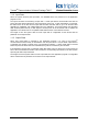
TrustedTM Communication Software Package T8017 2.5. Peer to Peer Configuration Example 3 Peer Network 1 Controller 1 Processor Module Comm Interface Module Comm Interface Module Peer Network 2 239.255.1.1* 10.10.1.4 10.10.1.1 10.10.3.4 239.255.1.1* 239.255.2.1* 239.255.2.1* 10.10.2.4 10.10.4.4 10.10.2.1 Comm Interface Module Comm Interface Module Controller 2 Processor Module Comm Interface Module Comm Interface Module Controller 4 Processor Module Controller 5 10.10.1.2 10.10.3.5 239.
TrustedTM Communication Software Package T8017 2.5.1. Controller setting summary Dual Peer to Peer Net Control, network 1 subnet 1. dxpnc40 – CONTROL rack Controller 1 Controller 2 Controller 3 Controller 4 CHASSIS 1 1 1 1 SLOT 7 7 7 7 NETWORK_ID 1 1 1 1 SUBNET_ID 1 1 1 1 PEER_ID 1 2 3 4 RESPONSE_TMO 0 0 0 0 REFRESH_TMO 2000 2000 2000 2000 TX_DATA_TMO 500 500 500 500 Variable 1 TRUE TRUE TRUE TRUE Variable 2 FALSE FALSE FALSE TRUE PEER_IP_01 10.10.1.
TrustedTM Communication Software Package T8017 Dual Peer to Peer Net Control, network 1 subnet 2. dxpnc40 – CONTROL rack Controller 1 Controller 2 Controller 3 Controller 4 CHASSIS 1 1 1 1 SLOT 8 8 8 8 NETWORK_ID 1 1 1 1 SUBNET_ID 2 2 2 2 PEER_ID 1 2 3 4 RESPONSE_TMO 0 0 0 0 REFRESH_TMO 2000 2000 2000 2000 TX_DATA_TMO 500 500 500 500 Variable 1 TRUE TRUE TRUE TRUE Variable 2 TRUE FALSE FALSE FALSE PEER_IP_01 10.10.2.1 10.10.2.1 10.10.2.1 10.10.2.
TrustedTM Communication Software Package T8017 Dual Peer to Peer Net Control, network 2 subnet 1. dxpnc40 – CONTROL rack Controller 4 Controller 5 CHASSIS 1 1 SLOT 7 7 NETWORK_ID 2 2 SUBNET_ID 1 1 PEER_ID 1 2 RESPONSE_TMO 0 0 REFRESH_TMO 2000 2000 TX_DATA_TMO 500 500 Variable 1 TRUE TRUE Variable 2 TRUE FALSE PEER_IP_01 10.10.3.4 10.10.3.4 PEER_IP_02 10.10.3.5 10.10.3.
TrustedTM Communication Software Package T8017 Dual Peer to Peer Net Control, network 2 subnet 2. dxpnc40 – CONTROL rack Controller 4 Controller 5 CHASSIS 1 1 SLOT 8 8 NETWORK_ID 2 2 SUBNET_ID 2 2 PEER_ID 1 2 RESPONSE_TMO 0 0 REFRESH_TMO 2000 2000 TX_DATA_TMO 500 500 Variable 1 TRUE TRUE Variable 2 FALSE TRUE PEER_IP_01 10.10.4.4 10.10.4.4 PEER_IP_02 10.10.4.5 10.10.4.
TrustedTM Communication Software Package T8017 2.5.2.
TrustedTM Communication Software Package T8017 2.6. Suggested Configuration The Peer to Peer I/O board definitions for timeout parameters should be set appropriate to the peer system as described below. Equipment Parameter Description RESPONSE_TMO 0ms is recommended on a local network. REFRESH_TMO (Npeer x TX_DATA_TMO) TX_DATA_TMO Set to RESPONSE_TMO or 2mS, which ever is greater, multiplied by the maximum number of (dxpao + dxpdo) output boards in any single controller + 16ms.
TrustedTM Communication Software Package T8017 2.7. Peer Network Specification No. of Peer Networks per System Target Inter-application Response Single point change All points change P8 nx15ms + 2x(source + destination application scan) nx15ms(per 1000 digital points per node) + nx15ms(per 60 analogue points per node) + 2x(source + destination application scan) n=no. of nodes/systems on the network No.
TrustedTM Communication Software Package T8017 This page is intentionally blank Issue 10 Mar 08 PD-T8017 45