TrustedTM AN-T80020 Application Note Diagnostics Procedure This document provides: • A procedure for first-line diagnostics This explains how to gather the appropriate data for each situation. It is easy to lose evidence after a module or system failure. This procedure explains how to collect the evidence to give to a support engineer, who can use the rest of this document to diagnose the problem.
TrustedTM AN-T80020 Diagnostics Procedure Diagnostics Procedure Table of Contents Diagnostics Procedure..............................................................................................................................2 Table of Contents...................................................................................................................................2 First-line Diagnostics ...........................................................................................................
TrustedTM AN-T80020 Diagnostics Procedure Please do NOT send:...........................................................................................................................37 APPENDIX A. ERROR CODE DESCRIPTIONS....................................................................................38 Glossary ...............................................................................................................................................39 0x0000 Series Codes (Firmware and System) ......
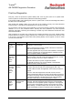
TrustedTM AN-T80020 Diagnostics Procedure First-line Diagnostics Every day, check the processor’s System Healthy LED. If this is green, there are no system faults. There may still be communications problems and field wiring problems. If the System Healthy LED is flashing red, there is a system fault. Look at the other diagnostic LEDs in the table on the next few pages. Each module has ‘Healthy’ LEDs, one for each slice of the module’s circuitry.
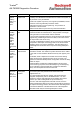
TrustedTM AN-T80020 Diagnostics Procedure LED colour Reason Procedure Processor 'System Healthy' LED is not steady green There is a system fault The 'System Healthy' LED is steady green when the complete system is healthy. The LED flashes red when there is a fault in the system, or the processor is not yet initialised. A fault in the system may be any of a long list of possibilities, but the processor current log will always show the reason. Collect the processor’s current system log.
TrustedTM AN-T80020 Diagnostics Procedure LED colour Reason Procedure A comms interface port is not showing LED activity No comms Serial ports should be flickering red/green or yellow if active. Ethernet ports should be flickering red/green or yellow if active and steady green or off when inactive. Flickering red or green only indicates one way communications. Red is transmit, green is receive.
TrustedTM AN-T80020 Diagnostics Procedure Toolset Diagnostics If you need to find an I/O module fault code, use the Toolset to access the data in the system. The data also includes further data on the system, e.g. temperature, voltages, currents etc. Open the Toolset, using either your desktop shortcut or the Start menu ( Start | All Programs | Trusted | Toolset ). Open the application running in the system by double-clicking on its name.
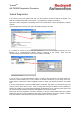
TrustedTM AN-T80020 Diagnostics Procedure Select Debug | Debug. A long thin window entitled IEC1131 TOOLSET – (application) – Debugger should appear. This will have a bold black line of text giving the state of the application. This window is called the Debugger window and it is the key to all online controls. To disconnect from the system, close this window and all other online windows will also close. If the black line of text says RUN, you are connected to the system. Go on to the next page.
TrustedTM AN-T80020 Diagnostics Procedure You will see a window similar to the ‘Programs’ window, now called the ‘Debug Programs’ window. This gives access to online diagnostics. You cannot close this window. To end an online session, close the Debugger window. Open the I/O connection table by clicking on the icon shown above or menu Project | I/O connection. Each module in the system has an equipment definition. Imagine this as a marshalling terminal rail, with several blocks of terminals.
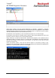
TrustedTM AN-T80020 Diagnostics Procedure The error code number is shown in decimal (base 10). However, the codes are defined in hexadecimal (base 16) and the number needs to be converted. Open the Windows Calculator. Select the Scientific view (View | Scientific). Select ‘Dec’ (decimal) as shown above. Type the error code number. Select ‘Hex’ (hexadecimal). The calculator will convert the number. Look up the hexadecimal number in the table in this manual.
TrustedTM AN-T80020 Diagnostics Procedure Other data on Equipment Definitions All modules provide information on temperature, in many cases at several points throughout the module. Note that these temperatures are ranged differently, e.g. on the processor 1°C = 10 counts, but on the I/O modules, 1°C = 256 counts. The operating range of all native 8000 series modules (except the Gateway module which contains a PC104 computer) is –5 to 60°C.
TrustedTM AN-T80020 Diagnostics Procedure Analysis Tool This application can collect command line diagnostics online from a live system. It can analyse the collected data and provide advice and reports. It can also analyse logs taken by the macro program Dumptrux in the same way. It can erase the system logs. The program installs itself by default into the same directory as the Toolset and other 8000 series software. It also provides the option of a desktop icon and a Quick Launch icon.
TrustedTM AN-T80020 Diagnostics Procedure Online The online comms setup allows Ethernet or serial connection. Choose the Ethernet IP address or serial port number as appropriate. Choose the automatic diagnostic collection option: 1) None This just makes a connection and opens the terminal. 2) Choose This collects enough data to discover the modules fitted in the system and takes only a few seconds. It then provides a picture or tree of the system which can be clicked on to get data from each module.
TrustedTM AN-T80020 Diagnostics Procedure Once the program has a connection, it will start the automatic collection option that was chosen. Leave the collection to run. It will report its progress in the bottom banner.
TrustedTM AN-T80020 Diagnostics Procedure Online Options Once the online collection has finished, more options are available on the Online menu. ‘Set the time/date’ allows you to set the clock in the system. You can enter a time/date using the middle ‘Time to set’ options, and click ‘Set this time’. Clicking ‘Copy and Set’ does both actions. ‘Copy computer time’ will put the current PC time and date into the ‘Time to set’ options.
TrustedTM AN-T80020 Diagnostics Procedure ‘Auto set time/date’ sets the time automatically from the computer’s clock. It firstly measures the delay between sending a new line and receiving a prompt, and then plans a moment to set the time every ten seconds. On setting the time, the new line is sent at a calculated moment before the second to attempt the most accurate time synchronization. Serial is the fastest medium with latencies of a few milliseconds; Ethernet latencies are at least twenty times longer.
TrustedTM AN-T80020 Diagnostics Procedure ‘Erase Logs’ deletes all system event logs. Do not erase any logs unless you are sure they are no longer necessary. For example: • The logs are too big to collect. Erase the logs, leave the system to run its diagnostic routines (24 hours), then collect the logs to inspect current problems. • Collect the logs once a month for an archive, and erase the logs after each collection to keep them small. The default option is to erase all logs in the system.
TrustedTM AN-T80020 Diagnostics Procedure System Graphic / Online Tree Window When you connect, the Analysis Tool will interrogate the system and make a clickable window of the system shape. If you hover over a module, the window title shows the module type and a pop-up ‘Tool Tip’ shows whether you have already collected from that module. A grey module has not been collected, a light blue module is being collected, and a dark blue module has been collected.
TrustedTM AN-T80020 Diagnostics Procedure Manual Command Entry You can type commands into the online window. This is recommended only if you are competent with the 8000 series systems and you know the command you need, or the first-line diagnostics specifically asks you to type these commands.
TrustedTM AN-T80020 Diagnostics Procedure Offline You can either: 1) analyse some data you have collected online (see above) or 2) open an existing log file (collected using the Analysis Tool, Dumptrux or a terminal program) or 3) open a file of analysed data previously made by this program. If you want to analyse your online data, use Online | Analyse Data. If you want to analyse a saved file, use File | Open log file.
TrustedTM AN-T80020 Diagnostics Procedure Once open, you see the System Health view. This shows a summary of advice given by the program and it is described later. File Menu The File menu provides basic tools as follows, depending on which view is shown: • Open log file: chooses a new file to open. (Ctrl-O will also work) • Open analysed data: opens a file created by the Save analysed data option below. It will open quickly because the analysis work is already done.
TrustedTM AN-T80020 Diagnostics Procedure Log View This shows the initial view of the whole file, as if it was in a text editor. Experienced engineers can search through the data for details that may not be captured by the reports. Use the Find menu to help with searching. Find Menu The Find menu has the following options for manual searching through the log. • Text … : simple text search as in Notepad, with similar options.
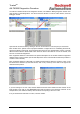
TrustedTM AN-T80020 Diagnostics Procedure Each I/O module has up to seven reports. Left-click on the module for the main report. This provides serial numbers, versions and the error codes currently reported on each module. These are the same error codes as found through the Toolset Diagnostics. Right clicking provides the system event logs on each slice (if the file includes them), and two or three data reports.
TrustedTM AN-T80020 Diagnostics Procedure Each event includes a timestamp, which is calculated from a millisecond count in the log. If the timestamp can't be determined, it is shown as time since startup or the beginning of the log. The logs contain no information on the year, so the Analysis Tool makes a best guess based on other data. For this reason, the year may be wrong. Entries are categorised and coloured in a similar way to the graphical system view – see page 22.
TrustedTM AN-T80020 Diagnostics Procedure Bookmarks If you click on a log event, you can add a bookmark and a comment by choosing the Bookmark menu option. The event in the log then has a bookmark icon. Bookmarks and their comments are saved with the report data when you choose ‘Save analysed data’, so that you can send the analysed data file for further investigation. When there are bookmarks, the View menu has an extra option ‘Bookmarks’.
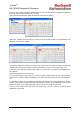
TrustedTM AN-T80020 Diagnostics Procedure Other data from the I/O modules is available under the Data branch. • Channel Data is useful for comparing the measurements or states of the three slices. Note that log data collection results in snapshots from the three slices at different times, so differences may just reflect changing channel states.
TrustedTM AN-T80020 Diagnostics Procedure • Housekeeping Data provides system circuit measurements of voltage, current and temperature. This provides more data than is available through the Toolset HKEEPING board.
TrustedTM AN-T80020 Diagnostics Procedure • Threshold Data provides the input state measurement thresholds operating in the module.
TrustedTM AN-T80020 Diagnostics Procedure Module Versions This is a simple report of all the module firmware versions in the system. It is useful for collecting serial numbers, firmware versions and module types and gives a quick idea of the shape of the system.
TrustedTM AN-T80020 Diagnostics Procedure System Health This report collects all the most important advice that the Analysis Tool has provided into one report. It is a global report of the health and state of the system. You can use this report as a single point of advice for the whole system. It reports all current faults on I/O modules, advises on firmware upgrade needs, reports communication configuration problems and I/O module configuration problems.
TrustedTM AN-T80020 Diagnostics Procedure Bookmarks If you click on an entry, you can add a bookmark and a comment by choosing the Bookmark menu option. The entry then has a bookmark icon. Bookmarks and their comments are saved with the report data when you choose ‘Save analysed data’, so that you can send the analysed data file for further investigation. When there are bookmarks, the View menu has an extra option ‘Bookmarks’.
TrustedTM AN-T80020 Diagnostics Procedure Main Processor System Logs MON 2009-03-23 17:02:56 25 Cfg: Configuration file loaded.
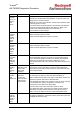
TrustedTM AN-T80020 Diagnostics Procedure IMB: Permanent fatal fault (MBCU) Chassis 3 Slot 2 The I/O module has shut down NIO: Slice state discrepancy - Chassis 2 Slot 11 Slice A This slice is in a different state to the other two Self Test: FCR A(B,C) BACKGROUND monitor - permanent fault A confirmed discrepancy was detected between memory data on the processor’s three slices.
TrustedTM AN-T80020 Diagnostics Procedure FPS: Module ejectors open The processor’s ejector tabs are open (or the ejector switches are faulty) SYS: Module power fail The processor has been turned off or removed (usually the last entry in a backup log) Issue 12 Feb 11 AN-T80020 34
TrustedTM AN-T80020 Diagnostics Procedure Clearing the MP Non-Volatile RAM (NVRAM) Memory This procedure is often abused and is only necessary when changing the system.INI module allocation with processor build 122 (see TN20061) or when a processor suffers from ‘GALPAT’ errors after losing power on startup (see TN20014). Do not erase the NVRAM for any other purpose because it will delete all diagnostic evidence in the processor.
TrustedTM AN-T80020 Diagnostics Procedure Action on Processor Shutdown The 8000 series system is designed to be fault tolerant, with triplicated circuits allowing simple 2-outof-3 voting at very high speed. It is therefore able to identify and isolate faults which cause one slice to be different. However, there are always common cause failure modes in any safety system. The 8000 series system is designed to shut itself down if it cannot guarantee its integrity.
TrustedTM AN-T80020 Diagnostics Procedure Processor System Event Logs If an 8000 series processor shuts down, the reason may be documented in the processor's event log. The processor keeps two event log files. One is the current log and is written to during operation. On starting, the processor swaps to the other log file and leaves the original file as a record of the events before it last shut down.
TrustedTM AN-T80020 Diagnostics Procedure APPENDIX A. ERROR CODE DESCRIPTIONS This section provides detailed descriptions for each of the error codes reported by I/O modules, including what is wrong and what to do. Error codes are described in four digit hexadecimal numbers. The first two digits describe the category of error, and for many categories the last two digits are a “subcode”, narrowing down which part of the module was noted as faulty.
TrustedTM AN-T80020 Diagnostics Procedure Glossary A/D Analogue to Digital Converter (or ADC) APP Module Application firmware ASCII Standard text character codes ASIC Application Specific Integrated Circuit BOOT Initial code run by module on startup, or startup state BSU Bus Slave Unit; protocol circuit communicating to the MP over the IMB BTM Bottom (of an output switch pair) CLI Command Line Interpreter; text based interface to system components (human and internal) CONFIG A slice is read
TrustedTM AN-T80020 Diagnostics Procedure OVI, OVC Overcurrent trip OVP Over Potential (also OVV) OVV Overvoltage trip (also OVP) PIC Programmable Intelligent Computer – microcontroller chip used here for channel control PRM Programmable Ramp Module(?) – for test patterns RAM Random Access Memory REG Regulated RIO Real Time I/O (operating system) Semaphore Communication token SHUTDOWN A slice has switched all its I/O to the configured shutdown state SSL Smart Slot Link SYNC Synchronisat
TrustedTM AN-T80020 Diagnostics Procedure 0x0000 Series Codes (Firmware and System) Codes 0x0001 to 0x01FF Modules: All Codes 0x0200 to 0x02FF Modules: All Codes 0x0400 to 0x04FF Modules: All except 8480 (see note) IMB FATAL ERROR 0x07nn (to 0x073F) Modules:All nn: Error flags in 6 bit word: 1: BSU Finite State Machine error 2: Timeout error 4: Slot error 8: Framing error 10: Symbol error 20: Packet error IMB_DOUT_RESET 0x0740 Modules: 8442 The other modules report this fault as 0x8740.
TrustedTM AN-T80020 Diagnostics Procedure FIA_SLICE_STATE_DISCREP 0x0805 Modules:All except 8442 and 8480 If a slice is commanded to change to a new state, and this state is different to the command sent to the other two states (‘Byzantine’ voting), it will increment a counter every 300ms. After 400 counts (2 minutes), it will signal this fault and go OFFLINE because its state does not agree with the other two slices. This indicates a bus interface fault; the module should be returned for repair.
TrustedTM AN-T80020 Diagnostics Procedure 0x1000 Series Codes (Host Interface Unit) Some of these codes refer to ‘upstream’ and ‘downstream’ slices. The definitions depend on the circuit concerned, but for the 0x1000 and 0x2000 codes relating to inter-slice communications, the definitions are: On slice A: ‘upstream’ = slice B, ‘downstream’ = slice C On slice B: ‘upstream’ = slice A, ‘downstream’ = slice C On slice C: ‘upstream’ = slice A, ‘downstream’ = slice B.
TrustedTM AN-T80020 Diagnostics Procedure HIU_ISL_CRC_ERR 0x1008 Modules:All except 8442, 8472, 8473, 8480 This indicates a data check failure on data from the other slices over the inter-slice link. Detects a corrupted ISL link, including faulty ISL RAM in the sending or receiving slice. If a slice is offline, these faults are common in the remaining two slices and can be ignored. If all slices are online, and the fault is persistent, return the module for repair.
TrustedTM AN-T80020 Diagnostics Procedure HIU_ISL2_SYNC_TST 0x103n Modules:8442,8472, 8473 Subcode: n = discrepant slice ID (0, 1, 2 for slice A,B,C) Detects latent faults in the inter-slice link voter logic and discrepancy detection logic by injecting discrepant data every minute. If a slice has gone offline, this fault may appear on the other two slices and may be ignored. Otherwise return the module for repair.
TrustedTM AN-T80020 Diagnostics Procedure 0x2000 Series Codes (Host Interface ASIC) Some of these codes refer to ‘upstream’ and ‘downstream’ slices. The definitions depend on the circuit concerned, but for the 0x1000 and 0x2000 codes relating to inter-slice communications, the definitions are: On slice A: ‘upstream’ = slice B, ‘downstream’ = slice C On slice B: ‘upstream’ = slice A, ‘downstream’ = slice C On slice C: ‘upstream’ = slice A, ‘downstream’ = slice B.
TrustedTM AN-T80020 Diagnostics Procedure ISL_SEQ_ERR 0x209n Modules: 8480 Subcode: n = discrepant slice Sequence counter discrepancies on communications with another slice. Return the module for repair. Action:Slice fault (1 = ‘upstream’, 2 = ‘downstream’) ISL_DSBL_ERR Request received from other slices to force this slice offline. 0x20A0 This is probably a secondary result of earlier faults, e.g. an 0x8741 from the processor shutting down the slice.
TrustedTM AN-T80020 Diagnostics Procedure 0x3000 Series Codes (Field Interface ASIC) FIA_INVALID_IMAGE 0x3000 Modules:All This test checks the application firmware in FLASH on loading the Field Interface firmware. Detects a FLASH memory fault or missing firmware. The module will stay in boot mode. Return the module for repair. Action:Slice will not boot FIA_INVALID_IMAGE_CRC 0x3001 Modules:All This test performs a CRC check on the firmware in FLASH on loading the Field Interface firmware.
TrustedTM AN-T80020 Diagnostics Procedure 0x4000 Series Codes (Module firmware operation) APP_INVALID_IMAGE 0x4000 Modules:All This test checks the application firmware in FLASH on either loading the boot code or the application firmware. Detects a FLASH memory fault or missing firmware. The module will stay in boot mode. If loading application firmware, erase and try again, else return the module for repair. If loading boot firmware, return the module for repair.
TrustedTM AN-T80020 Diagnostics Procedure 0x5000 Series Codes (Input Field Interface Unit) FIU_HFIU_RAM_FAIL 0x5000 Modules:Input, 8480 OFIU_FIA_SYNC_FAULT 0x500n Subcode: n = quadrant (0 to 3) Modules:8472, similar in 8442 FIU_HIA_SYNC_FAULT 0x5001 Modules:Input FIU_FIA_SYNC_FAULT (input modules) 0x5002 Detects serious errors in field interface/Host interface data transfer RAM such as address/data faults. Return the module for repair.
TrustedTM AN-T80020 Diagnostics Procedure HSIU_RAM_PAGE_FAULT 0x5006 Modules:8442 OFIU_PLL_FAULT 0x5006 Modules:8472 Detects any fault in free RAM that is related to RAM paging. Return the module for repair. Action:Slice OFFLINE Detects faults in the field interface timing control circuitry (the test schedule is locked to the AC cycle). These faults may be a secondary effect of other faults. If the fault is persistent, return the module for repair.
TrustedTM AN-T80020 Diagnostics Procedure SFIU_TRIP_AUTO_RESET 0x502n Subcode: n = output (0 to 5) Modules:8442 SFIU_TRIP_AUTO_TRIP 0x503n Subcode: n = output (0 to 5) Modules:8442 SFIU_TRIP_AUTO_RE_TRIP 0x504n Subcode: n = output (0 to 5) Modules:8442 Auto-reset of a 1oo3 trip that persisted for too long. This may be the byproduct of other faults. If the fault is persistent, return the module for repair. Action:Slice fault 2oo3 trip that co-erced a 3oo3 trip to maintain congruency.
TrustedTM AN-T80020 Diagnostics Procedure IFIU_CHANNEL_FAULT 0x52nn or 0x52mn Modules:Input, 8442, 8480 Detects a faulty input channel. Faults could be on the field interface adapter or due to field effects; later firmware is more robust to field faults. For inputs and 8480: subcode nn = channel, 0x00 to 0x29 (0 to 41) (channels 0 and 41 are internal reference channels.) For 8442: subcode mn, m = quadrant 0 – 2, n = speed input channel 0 – 8. Swap the module and test it in an unused unconnected slot.
TrustedTM AN-T80020 Diagnostics Procedure OFIU_IMON_AV_DC_ERR 0x57mn Modules:8472 Subcode: Detects offset errors in the current monitor op-amp. This can be caused by a gain/offset resistor fault or op-amp fault. If the fault is persistent, return the module for repair.
TrustedTM AN-T80020 Diagnostics Procedure 0x6000 Series Codes (Output Field Interface Unit) Modules:Output (not 8442,72 or 80) Detects a stuck bias signal in the Group Fail Safe Switch (GFSS). This fault may also be caused by channel current noise, which may be caused by poor zero volt referencing or nonlinear loads (the test is less sensitive from TUV 3.5 firmware). For persistent faults, check the load linearity and try a replacement module.
TrustedTM AN-T80020 Diagnostics Procedure OFIU_CMD_RESP_ERR 0x606n Modules:Output Subcode: 8471, 8442: n = output group 0 to 3 Detects a fault in the safety-critical command path. This is usually caused by a discrepancy in the MP command to each HIU slice or a fault in the circuits involved in passing the output commands. Swap the module and try in another slot (it usually clears after a restart). If there are still similar (communications) faults, return the module for repair.
TrustedTM AN-T80020 Diagnostics Procedure OFIU_ LNK_DSCRP_CMD_ERR 0x60Bn Modules:8472, 8442 Subcode: n = quadrant (0 to 3) or all quadrants (5) If this fault is reported on a single quadrant, it indicates an open/shorted command between an HIU slice and the FIA of that quadrant. If the fault is persistent, return the module for repair. If the fault is reported on all quadrants (60B5), it indicates a discrepancy between the switch command registers on the HIU slices.
TrustedTM AN-T80020 Diagnostics Procedure Some 6nnn series faults can occur on 8442 modules at firmware release 3.5 when some or all Speed Output FTAs are not fitted, despite ‘SOFTA not present’ configured in the INI. Firmware build 133 (TUV 3.5.1) properly gates out these diagnostic tests when there is no SOFTA. 8442 module outputs and the Speed Output FTAs must be considered part of the same circuit; if replacement of one part does not cure the fault, try replacing the other part.
TrustedTM AN-T80020 Diagnostics Procedure SFIU_RELAY_IMON_TST 0x63mn Modules:8442 This tests the current flowing in a relay on a speed output FTA during switching tests. Replace and return the FTA when possible. Action:Slice fault Subcode: mn: m = quadrant (0 to 3) + current monitor (0 or 4 for #1 or 2), n = output (0 to 5) SFIU_RELAY_IMON_ERR 0x64mn Modules:8442 Current is measured in a relay coil when it should be de-energised or vice versa on the Speed Output FTA.
TrustedTM AN-T80020 Diagnostics Procedure OFIU_DATA_FAULT 0x67nn Modules:8448 Subcode:nn = channel, 0x00 to 0x27 (1 to 40) SFIU_RELAY_CONTACT_ XTALK_FAULT 0x67mn This test provides a high level of integrity for all ADC data (voltage/current monitoring and HKAD). It detects faults in the ADCs (excluding the input multiplexer) and the data path between the ADCs and HIU RAM. This test is necessary on an 8448 because the voltage and current monitoring is used for inputs. Return the module for repair.
TrustedTM AN-T80020 Diagnostics Procedure OFIU_I_ERR 0x69nn Modules:Output except 8442,8480 8472: 69mn, m = (see right), n = channel (0 to F) Others: 0x69nn This test indicates a fault in the field channel/quadrant/group current measurement. Return the module for repair. Action:Slice OFFLINE except 8472 (slice fault) 8472: m = quadrant (0 to 3) + error type: 0 = measurement at range limit, 4 = imbalance between the two circuit legs, 8 = discrepant or unknown.
TrustedTM AN-T80020 Diagnostics Procedure OFIU_SMON_ERR 0x6Bmn Modules: 8472 Subcode: m = error type (see right), n = channel (0 to F) Detects unknown switch states, partial switch open/circuit, undervoltage or faults in diagnostic circuits, based on a measurement of the conductance of each switch (SMON = switch monitor). Each channel has four switches.
TrustedTM AN-T80020 Diagnostics Procedure SFIU_RELAY_DRIVE_XTALK Crosstalk between relay commands or diagnostics. 0x6Cmn (m=0,1,2,3) These faults are most likely to be on the module but may be on the SOFTA. Replace the module, and if the same fault codes appear on the next module, replace the SOFTA. Modules: 8442 Subcode: mn: m = quadrant (0 to 3) Action:Slice fault n = output 0 – 5 SFIU_RELAY_IMON_XTALK Crosstalk between relay current monitor circuits.
TrustedTM AN-T80020 Diagnostics Procedure INPUT_CHANNEL_OVC 0x6Enn Modules:8448, 8449 Subcode:nn = channel, 0x00 to 0x27 (1 to 40) SFIU_VMON_QUAD_DISCREP 0x6Emn Modules:8442 Subcode:m = (see right), n = group (0 to 2) This detects an over-current trip on an input channel. Input channels should not have over-current trips; this implies the channel output circuits have energised. Return the module for repair. Action:Slice fault Detects discrepancies in the voltage measurement in the relay output circuits.
TrustedTM AN-T80020 Diagnostics Procedure 0x7000 Series Codes (Processor generated) All 7000 series faults are created by the processor when it notes a problem on a module’s slice. The I/O module relies on the processor to log these faults.
TrustedTM AN-T80020 Diagnostics Procedure MP_CONFIGURATION_ERROR 0x7300 Modules:All This fault indicates that the configuration data (from the System.INI file) on this slice is discrepant with respect to the other two slices. After loading the configuration data, the processor compares the CRC data checks returned from the three slices. If they are different, this fault is raised on the discrepant slice (or all slices if there is a three-way discrepancy).
TrustedTM AN-T80020 Diagnostics Procedure MP_BIU_TRANSIENT_ERROR 0x7402 Modules:All This indicates a bus discrepancy due to an I/O module fault. It may also be caused by expander module or bus faults. Faults appearing on the same slice on several modules in a chassis indicates expander module or bus faults. If the fault appears on only one module, and it returns repeatedly after pressing Reset, return the module for repair.
TrustedTM AN-T80020 Diagnostics Procedure 0x8000 Series Codes (General non-resettable) All faults above 8000 cannot be reset using the processor’s Reset pushbutton. They are either indicating a failed startup or a fault found in the operational logic circuits through background testing. Codes 0x8400 to 0x8402 Modules: 8480 FIA_INVALID_IMAGE 0x8500 Modules:All FIA_INVALID_IMAGE_CRC 0x8501 Modules:All These indicate faults in programming the host interface ASIC. The module will fail to start.
TrustedTM AN-T80020 Diagnostics Procedure FIA_NOT_PRESENT 0x8801 Modules:All Appears on startup. Detects a missing or misaligned field interface assembly or ribbon cable. It also detects faults in the field interface power system that result in little or no current flow from the host interface, or a faulty current monitor. The slice will not boot. Re-insert the module; if it fails again, return the module for repair. FIA_POWERUP_ERROR 0x8802 Modules:All Appears on startup.
TrustedTM AN-T80020 Diagnostics Procedure Self Test Cycle Times The 8000 Series diagnostics tests occur at different intervals. Some faults cause an immediate error, and some can take hours before they are reported. Many faults are filtered by requiring a number of successive faults to cause an error, with a test pass decrementing the fault filter counter. Therefore, some occasional transient faults may be ignored. Main processor diagnostics are complete in no more than 24 hours.